FIRST® (For
Inspiration and Recognition of Science and Technology) was founded by inventor
Dean Kamen to inspire young people’s interest in science and technology. As a robotics
community that prepares young people for the future, FIRST is the world’s leading youth-serving
nonprofit advancing STEM education. For 30 years, FIRST has combined the rigor of STEM learning with
the fun and excitement of traditional sports and the inspiration that comes
from community through programs that have a proven impact on learning,
interest, and skill-building inside and outside of the classroom. FIRST
provides programs that span a variety of age groups:
•
FIRST® Robotics Competition for grades 9-12,
ages 14-18
•
FIRST® Tech Challenge for grades 7-12, ages
12-18
•
FIRST® LEGO® League for grades Pre-K-8,
ages 4-16
o
FIRST® LEGO® League Challenge for
grades 4-8 (ages 9-16, ages vary by country)
o
FIRST® LEGO® League Explore for
grades 2-4 (ages 6-10)
o
FIRST® LEGO® League Discover for
grades Pre-K-1 (ages 4-6)
Please visit the FIRST
website for more information about FIRST and its programs.
In October 2019, Dr. Woodie Flowers, an innovator in design
and engineering education and a Distinguished Advisor to FIRST and
supporter of our mission, passed away. As thousands of heartfelt tributes to
Woodie have poured in from around the world, it is clear his legacy will live
on indefinitely through the gracious nature of our community and our ongoing
commitment to empowering educators and building global citizens.
Figure
1‑1 Dr. Woodie Flowers, 1943-2019

FIRST® Robotics Competition
combines the excitement of sport with the rigors of science and technology.
Teams of students are challenged to design, build, and program industrial-size robots and compete for awards, while they also create a team
identity, raise funds, hone teamwork skills, and advance respect and
appreciation for STEM within the local community.
Volunteer professional
mentors lend their time and talents to guide each team. It’s as close to
real-world engineering as a student can get. Plus, high school students gain
access to exclusive scholarship opportunities from colleges, universities, and
technical programs.
Each January at an event known as “Kickoff,” a new,
challenging game is introduced. These exciting competitions combine the
practical application of science and technology with the fun, intense energy,
and excitement of a championship-style sporting event. Teams are encouraged to
display Gracious Professionalism®, help other teams, and
cooperate while competing. This is known as Coopertition®.
In 2023, FIRST Robotics Competition is projected to reach approximately
80,000 high-school students representing approximately 3,300 teams. Teams come
from nearly every state in the United States, as well as many other countries.
FIRST Robotics Competition
teams will participate in 61 Regional Competitions, 94 District Competitions,
and 11 District Championships. In addition, approximately 600 teams will
qualify to attend the FIRST Championship in April 2023.
This year’s game, and this manual, were presented at the 2023
FIRST Robotics Competition Kickoff on
Saturday, January 7, 2023.
At the Kickoff, all teams:
•
saw the 2023 game, CHARGED UPSM presented by Haas, for the first time,
•
learned about the 2023 game rules and regulations, and
•
received a Kickoff Kit that provides a starting point for robot build.
Safety is always
paramount, and many rules are intended to establish norms at each event that
will mitigate injury risk to all participants.
Event staff have
the final decision authority for all safety-related issues within a venue.
Please refer to FIRST
Robotics Competition District and Regional Event web page for safety, conduct, etc. rules not specific to CHARGED UP
or limited to MATCH play. As with all violations in this document, any event
rules also carry the potential consequence of a YELLOW or RED CARD.
1.4
Gracious Professionalism®, a FIRST Credo
Gracious Professionalism® is part of the
ethos of FIRST. It’s a way of doing things that encourages high quality
work, emphasizes the value of others, and respects individuals and the
community.
Gracious Professionalism is not clearly defined for a
reason. It can and should mean different things to everyone.
Some possible meanings of Gracious Professionalism
include:
•
gracious attitudes and behaviors are win-win,
•
gracious folks respect others and let that respect show in their
actions,
•
professionals possess special knowledge and are trusted by
society to use that knowledge responsibly, and
•
gracious professionals make a valued contribution in a manner
pleasing to others and to themselves.
In the context of FIRST, this means that all teams
and participants should:
•
learn to be strong competitors, but also treat one another with
respect and kindness in the process and
•
avoid leaving anyone feeling as if they are excluded or
unappreciated.
Knowledge, pride, and empathy should be comfortably and
genuinely blended.
In the end, Gracious Professionalism is part of
pursuing a meaningful life. When professionals use knowledge in a gracious
manner and individuals act with integrity and sensitivity, everyone wins and
society benefits.

The FIRST spirit encourages doing high-quality, well-informed
work in a manner that leaves everyone feeling valued. Gracious Professionalism
seems to be a good descriptor for part of the ethos of FIRST. It is part of
what makes FIRST different and wonderful.
- Dr. Woodie Flowers, (1943 – 2019)
Distinguished
Advisor to FIRST
It is a good idea to spend time going over this concept with
your team and reinforcing it regularly. We recommend providing your team with
real-life examples of Gracious Professionalism in practice, such as when
a team loans valuable materials or expertise to another team that they will
later face as an opponent in competition. Routinely highlight opportunities to
display Gracious Professionalism at events and encourage team members to
suggest ways in which they can demonstrate this quality themselves and through
outreach activities.
At FIRST, Coopertition® is
displaying unqualified kindness and respect in the face of fierce competition. Coopertition
is founded on the concept and philosophy that teams can and should help and
cooperate with one another even as they compete. Coopertition involves
learning from teammates and mentors. Coopertition means competing always
but assisting and enabling others when you can.
Message from Woodie
Flowers Award Recipients
The Woodie Flowers
Award is the most prestigious mentoring award in FIRST. The award recipients
created an important message for all FIRST Robotics Competition teams to
consider as we tackle each season.
Performing at your best is important. Winning is
important. This is a competition.
However, winning with Gracious Professionalism and
being proud of what you have accomplished and how you have accomplished it is
more important. FIRST could create rules and penalties to cover almost any
scenario or situation, but we prefer an understandable game with simpler rules
that allow us to think and be creative in our designs.
We want to know that our partners and opponents are
playing at their best in every match. We want to know they are playing with
integrity and not using strategies based on questionable behaviors.
As you create your robots and award presentations,
prepare for competition and MATCH play, create and implement game strategies,
and live your daily lives, remember what Woodie said time and time again, and
let’s ‘Make your Grandmother proud.’
Woodie Flowers
Liz Calef (88)
Mike Bastoni (23)
Ken Patton (51, 65)
Kyle Hughes (27)
Bill Beatty (71)
Dave Verbrugge (5110, 67)
Andy Baker (3940, 45)
Dave Kelso (131)
Paul Copioli (3310, 217)
Rob Mainieri (812, 64, 498, 2735, 6833)
Dan Green (111)
Mark Breadner (188)
John Novak (16, 323)
Chris Fultz (234)
John Larock (365)
Earl Scime (2614)
Fredi Lajvardi (842)
Lane Matheson (932)
Mark Lawrence (1816)
Eric Stokely (258, 360, 2557, & 5295)
Glenn Lee (359)
Gail Drake (1885)
Allen Gregory (3847)
Lucien Junkin (118)
Matt Fagen (4253)
Christine Sapio (2486)
2023 Season Spirit of Volunteering: A Message from
the Chief Volunteers to the FIRST Community
There are two phrases which drive and motivate the
individuals that volunteer their time for FIRST: “Giving Back” and “Pay It
Forward”. Each year, you have the opportunity to help create the best-ever
experience for our mentors, coaches, students, and fellow volunteers. You can
do this by volunteering at a FIRST event.
Volunteering has enormous, lifelong impacts for
everyone involved. Every student, teacher, event volunteer, mentor, coach, and
family member learns and grows throughout the season as they interact with each
other. There are tremendous growth opportunities for all! Each volunteer
takes their experiences, adds in the FIRST Core Values, and makes the decision
to Pay It Forward by volunteering.
To our team members and mentors: remember that the
volunteers you interact with are giving up their most precious asset - their
time - to ensure that all teams have a fulfilling, fun, and memorable
competition. Volunteers are the lifeblood of FIRST, and without them, FIRST
would not be where it is today. We urge you to remember that Gracious
Professionalism is part of the ethos of FIRST. It's a way of doing things that
encourages high-quality work, emphasizes the value of others, and respects
individuals and the community. We strive to train each volunteer to exhibit
Gracious Professionalism at all times - we hope that you can reciprocate that
behavior - and create an environment where all feel welcome.
To our loyal volunteers, and everyone else that is
considering volunteering: we want to invite you to join us for the 2023 season.
There’s a lot to gain from volunteering and part of what makes it so much fun is:
• Seeing
capable students learning and growing
• Making
new friends with other awesome volunteers
• Being a
part of the magic that makes an event happen
• Sharing
FIRST with folks who didn’t know about it
• Taking
event experiences back to your team
• Learning
how to communicate with people outside of your normal circle
To our FIRST alumni: We need you! You know the impact
of FIRST in your life and the opportunity you’ve been given. We’re asking you
to Give Back and help the next generation to have the same opportunity. The
FIRST website has great resources for finding out how you can
get involved by giving a few hours or more!
We look forward to welcoming you!
Chief Volunteer
Coordinators – Laurie Shimizu & Sarah Plemmons
Chief FTAs –
James Cerar and Mark McLeod
Chief Field
Supervisors – Scott Goering & Ayla DeLaat
Chief Judge
Advisors – Cindy Stong & Allen Bancroft
Chief Referees –
Aidan Browne & Jon Zawislak
Chief Robot
Inspectors - Al Skierkiewicz & Chuck Dickerson
1.7
This Document & Its Conventions
The 2023 Game Manual is a resource for all FIRST
Robotics Competition teams for information specific to the 2023 season and the CHARGED
UPSM presented by Haas game. Its audience will find the following
detail:
•
a general overview of the CHARGED UP game,
•
detail about the CHARGED UP playing Field,
•
a description of how to play the CHARGED UP game,
•
game rules (related to safety, conduct, game play, inspection,
etc.), and
•
a description of how teams advance at 2023 tournaments and
throughout the season
All participants should also study the Event
Rules Manual as it details event rules and expectations that perpetuate from
season to season. That content complements, and carries the same weight as,
this document.
The intent of this manual is that the text means exactly,
and only, what it says. Please avoid interpreting the text based on assumptions
about intent, implementation of past rules, or how a situation might be in
“real life.” There are no hidden requirements or restrictions. If you’ve read
everything, you know everything.
Specific methods are used throughout this manual to
highlight warnings, cautions, key words, and phrases. These conventions are
used to alert the reader to important information and are intended help teams
in constructing a Robot that complies with the
rules in a safe manner.
Links to other section headings in this manual, external
articles, and rule references appear in blue
underlined text.
Key words that have a particular meaning within the context
of the FIRST Robotics Competition and CHARGED
UP are defined in the Glossary section and indicated in all caps throughout this document.
The rule numbering method indicates the section, subsection,
and position of the rule within that subsection. The letter indicates the
section in which the rule is published.
•
G for Section 7 Game Rules:
ROBOTS
•
H for Section 8 Game Rules:
Humans
•
R for Section 9 ROBOT
Construction Rules
•
I for Section 10 Inspection and
Eligibility Rules
•
T for Section 11 Tournaments
The following digit(s) represents the subsection in which
the rule can be found. The final digits indicate the rule’s position within
that subsection.
Figure 1‑2 Rule numbering method

Warnings,
cautions, and notes appear in blue boxes. Pay close attention to their contents
as they’re intended to provide insight into the reasoning behind a rule,
helpful information on understanding or interpreting a rule, and/or possible
“best practices” for use when implementing systems affected by a rule.
While blue boxes
are part of the manual, they do not carry the weight of the actual rule (if
there is an inadvertent conflict between a rule and its blue box, the rule
supersedes the language in the blue box).
Imperial dimensions are followed by comparable metric
dimensions in parentheses to provide metric users with the approximate size, mass,
etc. Metric conversions for non-rules (e.g. dimensions) round to the nearest
whole unit, e.g. "17 in. (~43 cm)” and “6 ft. 4 in. (~193 cm).” Metric
conversions in rules round such that the metric dimension is compliant with the
rule (i.e. maximums round down, minimums round up). The metric conversions are
offered for convenient reference only and do not overrule or take the place of
the imperial dimensions presented in this manual and the official drawings (i.e.
dimensions and rules will always defer to measurements using imperial units).
Rules include colloquial language, also called headlines, in
an effort to convey an abbreviated version of the rule or rule set. There are
two versions of headline formatting. Evergreen rules, or rules which are
expected to go relatively unchanged from season to season, are indicated with a
leading asterisk and their rule number and headline are presented in bold green text. “Relatively unchanged” means
that the overall intent and presence of the rule from season to season is
constant, but game specific terms may be updated as needed (e.g. changing
Power Cells to GAME PIECES in a rule about what
coaches may not contact during a match). These rules also start their respective
section, so their rule number is not expected to change from season to season. All
other rule headlines use bold blue text. Any
disagreement between the specific language used in the rules and the colloquial
language is an error, and the specific rule language is the ultimate authority.
If you discover a disparity, please let us know at firstroboticscompetition@firstinspires.org
and we will correct it.
Team resources that aren’t generally season specific (e.g.,
what to expect at an event, communication resources, team organization
recommendations, Robot transportation
procedures, and award descriptions) can be found on the FIRST Robotics
Competition website.
The CHARGED UP manual is originally and officially written
in English and is occasionally translated into other languages for the benefit
of FIRST Robotics Competition teams whose native language may not be
English.
A text-based English version can be provided only for use
with assistive devices and not for redistribution. For more information, please
contact the FIRST Robotics Competition Team Experience Specialist at frcteamadvocate@firstinspires.org.
In the event that a rule or description is modified in an
alternate version of this manual, the English pdf version as published on the CHARGED
UP - Season Materials web page is the commanding version.
Team Updates are used to notify the FIRST Robotics
Competition community of revisions to the official season documentation (e.g.
the manual, drawings, etc.) or important season news. Team
Update posts are scheduled as follows:
•
each Tuesday and Friday, starting on the first Tuesday after
Kickoff and ending on the Tuesday prior to Week 1 events
•
each Tuesday, starting Week 1 and ending the week of the final
District Championship events.
Team Updates are posted on the CHARGED
UP - Season Materials web page and are generally posted before 5 pm,
Eastern.
Generally, Team Updates follow the following convention:
•
Additions are highlighted in yellow. This is an example.
•
Deletions are indicated with a strikethrough. This is an
example.
The Question and
Answer System (Q&A) is a resource for clarifying the 2023
CHARGED UP Game Manual, Awards webpages, official
field drawings, and/or FIRST
Robotics Competition District and Regional Events web page content. Teams
can search for previously asked questions and responses or pose new questions.
Questions can include examples for clarity or reference multiple rules to
understand the relationships and differences between them.
The Q&A opens on January 11, 2023, 12:00 PM Eastern.
Details on the Q&A can be found on the CHARGED
UP - Season Materials web page. The Q&A may result in revisions to the
text in the official manuals (which are communicated using the process
described in Team Updates).
The responses in the Q&A do not supersede the text in
the manual, although every effort will be made to eliminate inconsistencies
between the two. While responses provided in the Q&A may be used to aid
discussion at each event, per Inspection & Eligibility Rules and REFEREE Interaction, Referees
and inspectors are the ultimate authority on rules.
If you have concerns about enforcement trends by volunteer authorities, please notify
FIRST at firstroboticscompetition@firstinspires.org.
The Q&A is not a resource for firm predictions on how a
situation will play out an event. Questions about the following will not be
addressed:
•
rulings on vague situations,
•
challenging decisions made at past events, or
•
design reviews of a Robot system
for legality.
Weak questions are overly broad, vague, and/or include no
rule references. Some examples of questions that will not be answered in the
Q&A are:
•
Is this part/design legal?
•
How should the Referee have ruled
when this specific game play happened?
•
Duplicate questions
•
Nonsense questions
Good questions ask generically about features of parts or
designs, gameplay scenarios, or rules, and often reference one or more relevant
rules within the question. Some examples of questions that will likely be
answered in the Q&A are:
•
A device we are considering using on the Robot comes with purple
AWG 40 wire, does this comply with R?? and R??
•
We’re not sure how to interpret how Rule G?? applies if blue Robot A does X and red Robot
B does Y, can you please clarify?
•
If a Robot does this specific
action, is it doing what this defined term is describing?
Questions from “FRC 99999” represent content asked by key
volunteers (e.g., Referees, Inspectors, etc.), answered by FIRST, and are
considered relevant to teams.


This is the moment to get energized
to innovate. From the machines that move us to the food that sustains us to the
wireless technologies that connect us, energy plays an essential role in
keeping our world running. During our 2022-2023 robotics season, FIRST®
ENERGIZE℠
presented by Qualcomm, our teams will reimagine the future of sustainable
energy and power their ideas forward. Innovation can’t wait.
This year, FIRST teams will address today’s global
challenges related to United Nations
Sustainable Development Goal #7,
focused on ensuring access to affordable, reliable, sustainable, and modern
energy for all. By encouraging FIRST participants to think about future energy
sustainability, we’re also empowering them to be the next generation of leaders
and innovators, tackling the world’s toughest challenges.

Figure 4‑1
CHARGED UP field and key elements
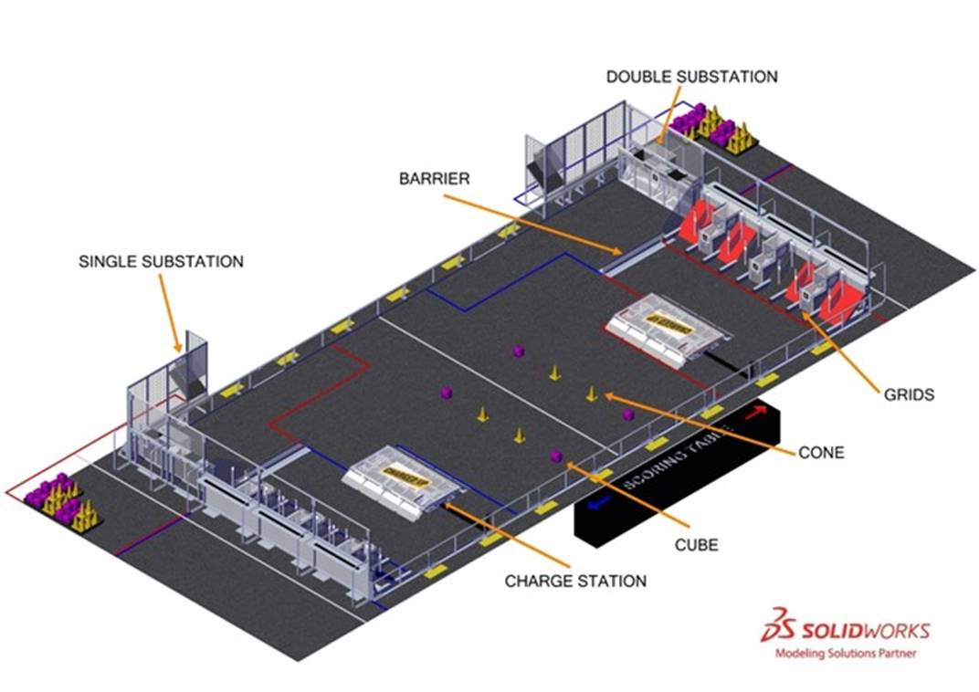
In CHARGED UPSM presented by Haas, two competing
alliances are invited to process game pieces to bring energy to their
community. Each alliance brings energy to their community by retrieving their game
pieces from substations and scoring it into the grid. Human players provide the
game pieces to the robots from the substations. In the final moments of each
match, alliance robots race to dock or engage with their charge station!
Each match begins with a 15-second autonomous period, during
which time alliance robots operate only on pre-programmed instructions to score
points by:
·
leaving their community,
·
retrieving and scoring game pieces onto the grid,
·
docking on or engaging with their charge station.
In the final 2 minutes and 15 seconds of the match, drivers
take control of the robots and score points by:
·
continuing to retrieve and score their game pieces onto the grid and
·
docking on or engaging with their charge station.
The alliance with the highest score at the end of the match
wins!

The ARENA includes all elements of the game
infrastructure that are required to play CHARGED UPSM presented by
Haas: the FIELD, GAME PIECES, and all equipment needed for FIELD control, ROBOT
control, and scorekeeping.
The ARENA is modular and assembled, used, disassembled, and
shipped many times during the competition season. It will undergo wear and
tear. The ARENA is designed to withstand rigorous play and frequent shipping.
Every effort is made to ensure that ARENAS are consistent from event to event.
However, ARENAS are assembled in different venues by different event staff and
some small variations occur. For details regarding assembly tolerances, please
refer to the 2023
ARENA Layout and Marking Diagram. Successful teams will design ROBOTS that
are insensitive to these variations.
Illustrations included in this section are for a general
visual understanding of the CHARGED UP Arena,
and dimensions included in the manual are nominal. Please refer to the official
drawings for exact dimensions, tolerances, and construction details. The
official drawings, CAD models, and drawings for low-cost versions of important
elements of the CHARGED UP Field are posted on
the CHARGED
UP - Playing FIELD web page on the FIRST website.
Figure 5‑1:
CHARGED UP

Each FIELD for CHARGED UP is an approximately
26 ft. 3½ in. (~802 cm) by 54 ft. 3¼ in. (~1654 cm) carpeted area bound by and
including the inward- and upward-facing surfaces of the guardrails,
inward-facing surfaces of the ALLIANCE WALLS, inward-facing surfaces of the
SINGLE SUBSTATION (excluding the PORTALS), and the outermost vertical and
diagonal polycarbonate surfaces of the DOUBLE SUBSTATION (excluding the
PORTALS).
Figure 5‑2 CHARGED UP Field
boundary
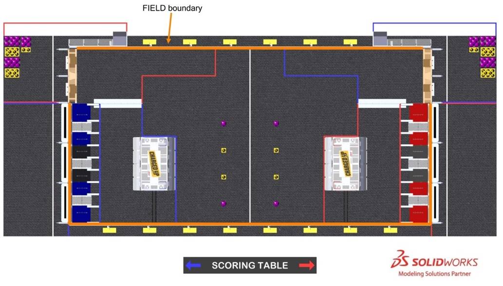
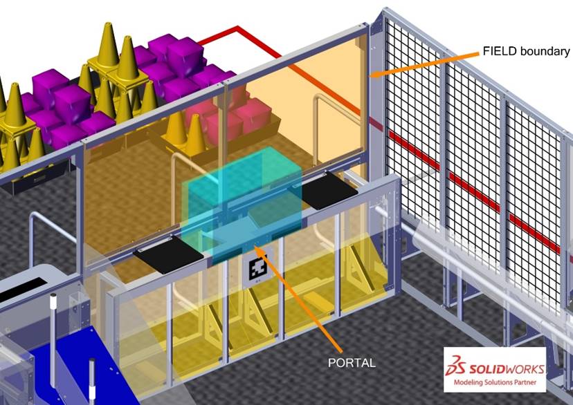
Figure 5‑3 CHARGED UP FIELD boundary at DOUBLE
SUBSTATION
The FIELD is populated with the following elements:
•
3 red GRIDS and 3 blue GRIDS located in front of their
corresponding ALLIANCE WALLS,
•
1 red CHARGE STATION and 1 blue CHARGE STATION located in their
corresponding COMMUNITIES,
•
1 red SINGLE SUBSTATION and 1 Blue SINGLE SUBSTATION located
along the guardrail in their corresponding SUBSTATION AREA,
•
1 red DOUBLE SUBSTATION and 1 blue DOUBLE SUBSTATION each located
in line with and adjacent to the opposing ALLIANCE WALL
•
2 BARRIERS, 1 separating each COMMUNITY from the opposing
ALLIANCE’S LOADING ZONE.
The surface of the Field is
low pile carpet, Shaw Floors, Philadelphia Commercial, Neyland II 20, “66561
Medallion” (please note that Neyland II carpet is not available for team
purchase and the closest equivalent is Neyland
III). The edge of the carpet is secured to the venue floor using 3M™ Premium
Matte Cloth (Gaffers) Tape GT2 or comparable gaffers tape.
Guardrails form the long edges of the Field. Guardrails are a 1 ft. 8 in. (~51 cm) tall
system of transparent polycarbonate supported on the top and bottom by aluminum
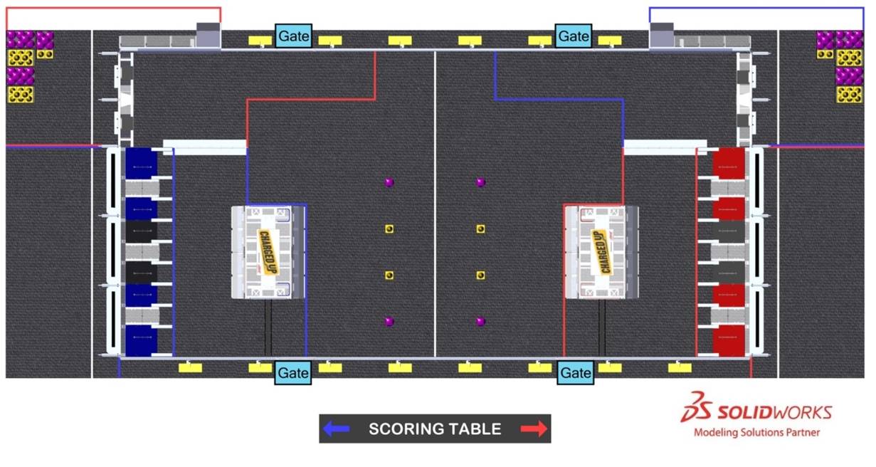
extrusion. There are 4 gates in the guardrail that allow access to the Field for placement and removal of Robots. The gate passthrough, when open, is 3 ft. 2
in. (~97 cm) wide. Gates are closed and shielded during the Match.
Figure 5‑4 Gate locations
There are 2 versions of guardrails
and Driver Stations used for competitions. 1 design
is reflected in the 2023
Official FIRST Field Drawings & Models. The other is designed
and sold by AndyMark. While the designs are slightly different, the critical
dimensions, performance, and expected user experience between them are the same
unless otherwise noted. Detailed drawings for the AndyMark design are posted on
the AndyMark
website. All illustrations in this manual show the traditional Field design.
Runs of black HDPE cable protectors extend from the guardrail
on the scoring table side of the Field to the
center of each CHARGE STATION. A cable protector run is made up of multiple
floor segments and an exit segment. The total length of the cable protector run
is 5 ft. 6 in. (~168 cm). The floor segments are ¾ in. (~19 mm) tall, 7 in. (~18
cm) wide, with ~45° lead in ramps on each leading edge and secured to the carpet
using hook fastener which increases the height to approximately ⅞ in. (~22
mm). Exit segments mount over the guardrail and are 1 ft. 8¾ in. (~53 cm) tall,
6 in. (~15 cm) wide and extend into the field 1¾ in. (~4 cm).
Figure 5‑5 Cable protector segment
Field areas, zones, and
markings of consequence are described below. Unless otherwise specified, the
tape used to mark lines and zones throughout the Field
is 2-in. (~5 cm) 3M™ Premium
Matte Cloth (Gaffers) Tape (GT2) or comparable gaffers tape.
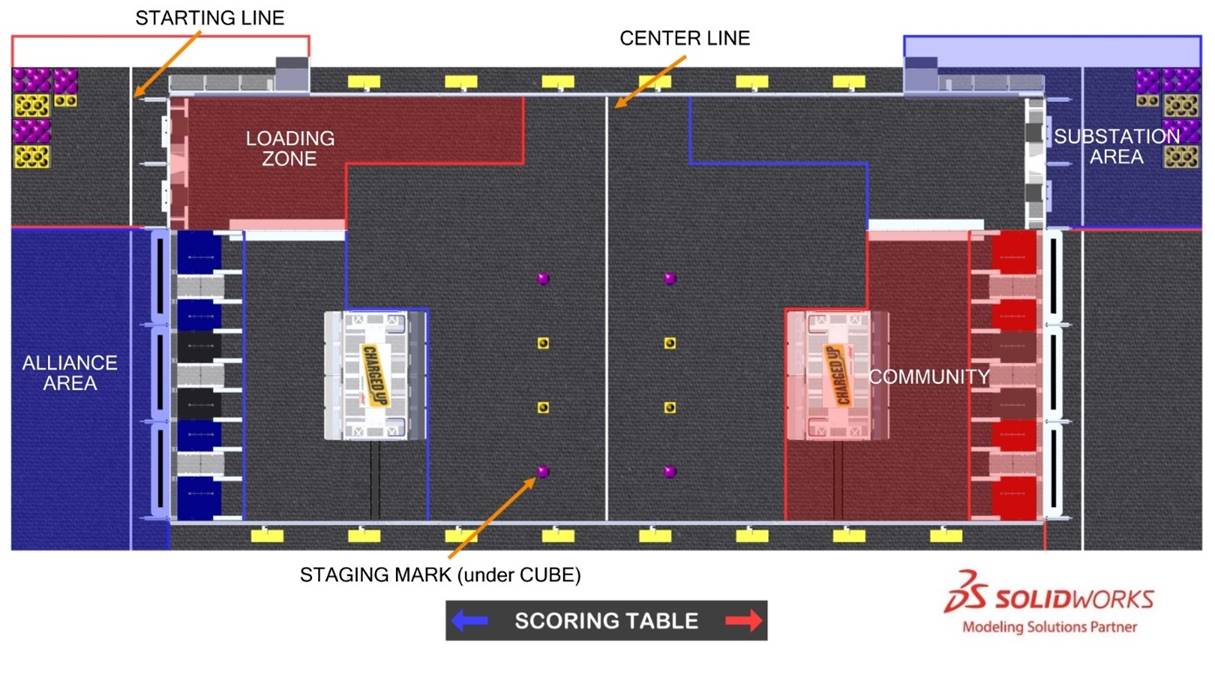
Figure 5‑6
Areas, Zones, and Markings
•
Alliance Area: a 20 ft. (~609 cm) wide by 9 ft. 10¼ in. (~300 cm) deep
infinitely tall volume formed by, and including the ALLIANCE WALL, the edge of
the carpet, and ALLIANCE colored tape.
•
CENTER Line: a white
tape line that bisects the length of the FIELD.
•
COMMUNITY: an 18 ft. (~549 cm) wide by 11 ft. ⅜ in. (~336 cm) to 16
ft. 1¼ in. (~491 cm) deep infinitely tall volume formed by the ALLIANCE WALL, the
plane defined by the BARRIER plastic, ALLIANCE colored tape, and the guardrail. The COMMUNITY includes the tape.
•
LOADING Zone: an 8 ft. 3 in. (~252 cm) wide by 11 ft.
¼ in. (~336 cm) to 22 ft. ¼ in. (~671 cm) deep infinitely tall volume formed by
the DOUBLE SUBSTATION, the plane defined by the BARRIER plastic, the guardrail,
and ALLIANCE colored tape. The LOADING ZONE includes the tape.
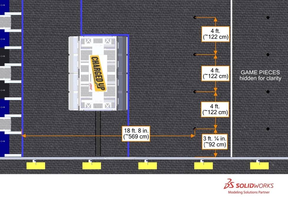
•
STAGING MARK: 1 of 8
marks used to identify starting locations for GAME PIECES. Marks are 4 in. (~10 cm) by 4 in. (~10 cm) crosses made
from black tape. Marks are spaced 4 ft. (~122 cm) apart from each other. Each
set of 4 marks is centered about the width of the COMMUNITY and is located 18
ft. 8 in. (~569 cm) from the far edge of the corresponding GRID tape as shown
in Figure 5‑7. A small, light mark may be added to each STAGING
MARK to distinguish STAGING MARKS from black tape used to patch carpet.
Figure 5‑7
STAGING MARK locations
•
Starting Line: a white tape line spanning the
ALLIANCE AREA and SUBSTATION AREA located 2 ft. 4 in. (~71 cm) from the face of
the ALLIANCE WALL to the near edge of the tape.
•
SUBSTATION AREA: a 12 ft. (~366 cm) wide by 18 ft. 7 in. (~566 cm) deep
infinitely tall volume formed by and including the DOUBLE SUBSTATION, the edge
of the carpet, the guardrail, the SINGLE SUBSTATION and ALLIANCE colored tape.
The SUBSTATION AREA includes the PORTALS and the tape.
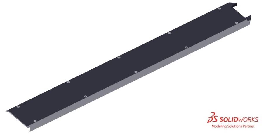
Figure 5‑8:
BARRIER
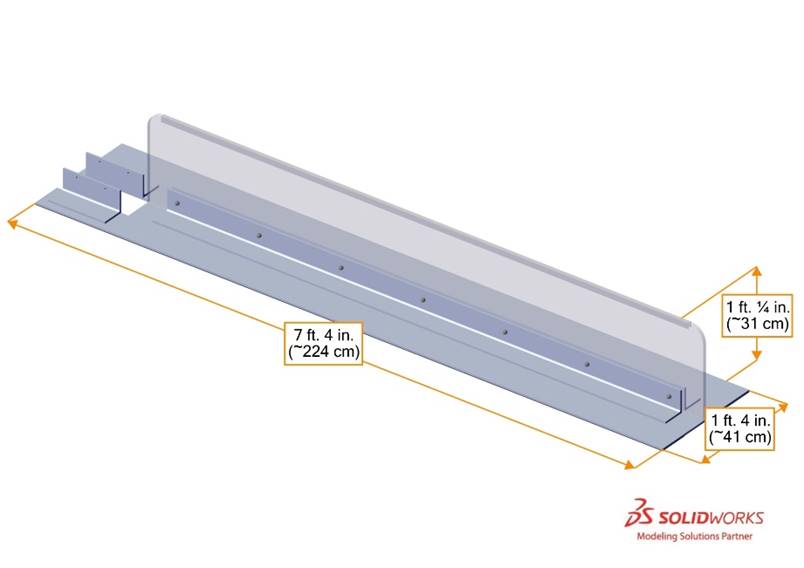
A BARRIER is a 7 ft.
4 in. (~224 cm) long assembly that separates each COMMUNITY from its adjacent
LOADING ZONE. The BARRIER has a base that is 1 ft. 4 in. (~41 cm) wide and ¼
in. (~6 mm) tall. The base supports a ½ in. (~13 mm) thick, 1 ft. ¼ in. (~31 cm)
tall polycarbonate wall. A strip of white tape traces the top of the BARRIER
plastic as shown in Figure 5‑8.
Figure 5‑9
LEVEL CHARGE STATION (click image to see field tour video)
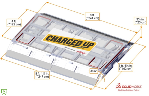
A CHARGE STATION is an 8 ft. 1¼ in.
(~247 cm) wide, 6 ft. 4⅛ in. (~193 cm) deep structure that is located in
each COMMUNITY such that its center is 8 ft. 2⅝ in. (~251 cm) from the far
edge of the GRID’S tape line and centered in the width of the COMMUNITY.
Each CHARGE STATION consists of the main pivoting frame, lead-in ramps, and the
support structure. The main pivoting frame is mounted to the base frame via a set
of 4 double hinges.
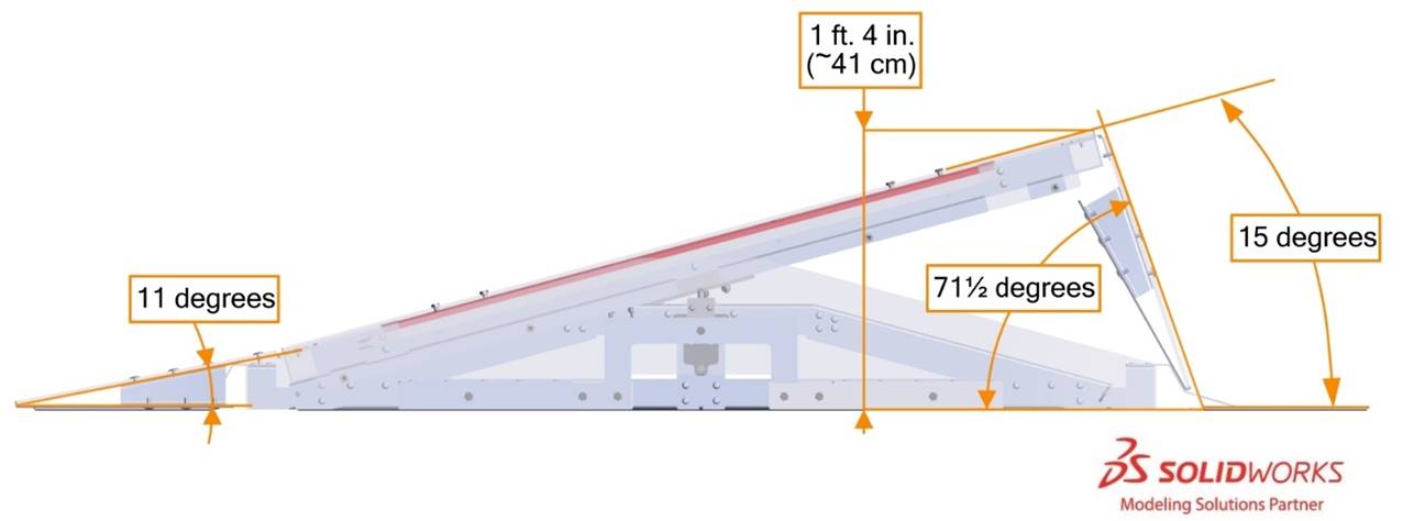
The main pivoting surface of a CHARGE STATION is 8 ft. (~244
cm) wide and 4 ft. (~122 cm) deep. It pivots +/- 15° about its long axis. When parallel to FIELD carpet, the top
polycarbonate surface is 9⅛ in. (~23 cm) above FIELD carpet as shown in Figure 5‑9. When pivoted to 15°, the
highest edge is 1 ft. 4 in. (~41 cm) above FIELD carpet. In normal operation, a
CHARGE STATION will naturally return to the middle of the LEVEL range. A CHARGE
STATION is considered LEVEL if it is within approximately 2½° of parallel to FIELD carpet.
Polycarbonate ramps are located on the long edges of each
CHARGE STATION. The ramps are 1 ft. 3⅛ in. (~39 cm) long and span the
full width of the CHARGE STATION. The ramps pivot and slide as the main
pivoting surface moves. When the CHARGE STATION top is LEVEL, the ramps are
tilted at an angle of approximately 34¼°
as shown in Figure 5‑9. When the CHARGE STATION is fully tilted, the
lower ramps are at an angle of approximately 11°
and the upper ramps are at an angle of approximately 71½°, as shown in Figure 5‑10.
Figure 5‑10
Fully tilted CHARGE STATION
The short edges of the CHARGE STATION feature guards that
restrict access to the underside of the structure.
Figure 5‑11 CHARGE STATION LEVEL lighting example
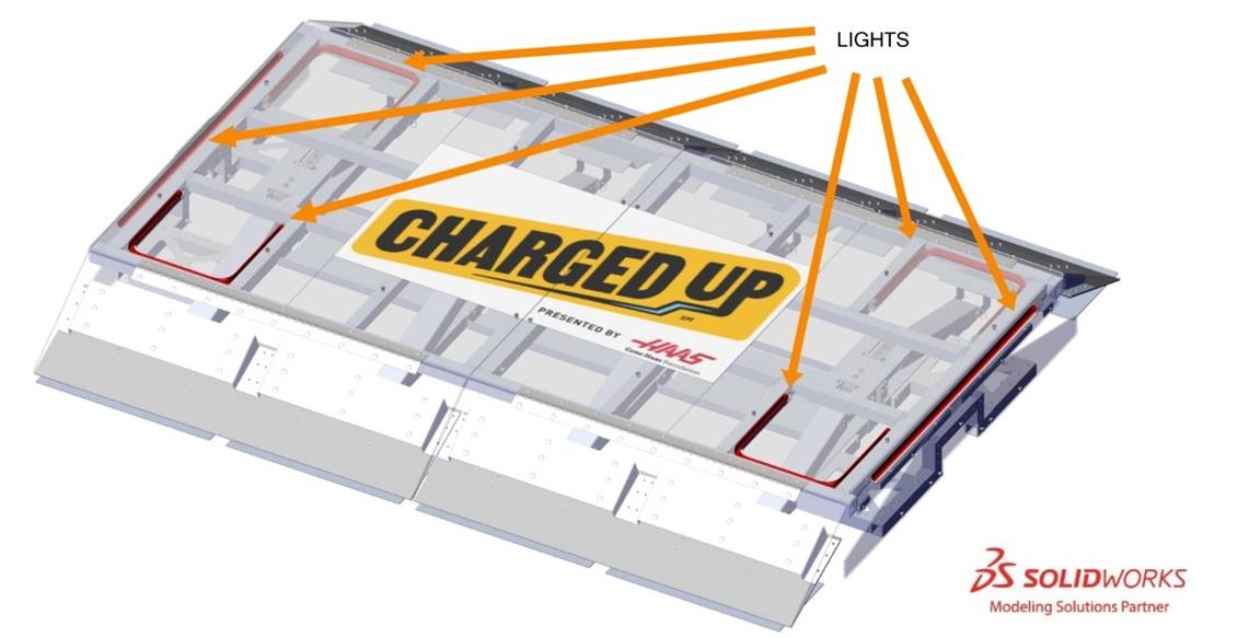
ALLIANCE colored lights located along the short edges of the
CHARGE STATION and at the 4 corners of the top surface indicate if it is LEVEL.
Table 5‑1
ENGAGED light states
|
Light State
|
Criteria
|
|
Off
|
Outside of a MATCH
In MATCH: CHARGE STATION is not
LEVEL
|
|
ALLIANCE
color
|
CHARGE STATION is LEVEL
|
Figure 5‑12 BLUE ALLIANCE GRIDS (click image to see
field tour video)
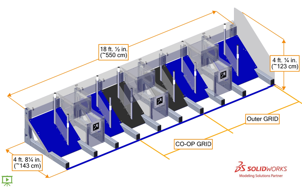
A collection of 3 GRIDS consisting of 2 outer GRIDS and a Coopertition
(CO-OP) GRID is located in front of each ALLIANCE WALL adjacent to the
guardrail and BARRIER. The full assembly is 18 ft. ½ in. (~550 cm) wide, 4 ft.
¼ in. (~123 cm) tall, and 4 ft. 8¼ in. (~143 cm) deep. A strip of
ALLIANCE-colored tape is included as part of the assembly of GRIDS and defines its
front plane.
Figure 5‑13 Individual GRID overall sizing
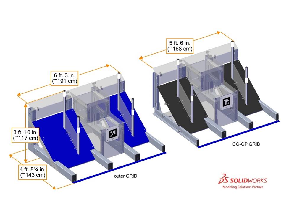
A GRID is a 3 ft. 10
in. (~117 cm) tall, 4 ft. 8¼ in. (~143 cm) deep assembly that includes the
ALLIANCE colored tape line. Outer GRIDS are 6 ft. 3 in. (~191 cm) wide. The
CO-OP GRID is 5 ft. 6 in. (~168 cm) wide.
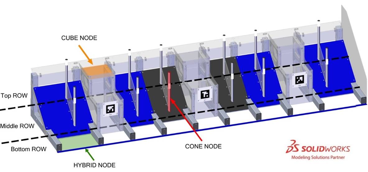
Each GRID contains 9 GAME PIECE scoring
locations called NODES:
·
3 HYBRID NODES
·
2 CUBE NODES, and
·
4 CONE NODES.
Each set of GRIDS is divided into 3 ROWS. A ROW is a series of 9 horizontally adjacent NODES where GAME PIECES can be
scored for a common number of points. The bottom ROW consists of 9 HYBRID
NODES. The middle ROW and top ROW each consist of 6 CONE NODES and 3 CUBE NODES.
Figure 5‑14 GRID NODES and ROWS
A HYBRID NODE is a 1 ft. 4 in. (~41 cm)
deep carpeted surface contained within the GRID. The 2 outermost HYBRID
NODES in each collection of GRIDS are 2 ft. 1¾ in. (~65 cm) wide and the rest
of the HYBRID NODES are 1 ft. 6½ in. (~47 cm) wide. HYBRID NODES have 5 in.
(~13 cm) tall dividers between them. A guardrail or BARRIER runs coincident to
the left and right outermost edges of a collection of GRIDS which limits access
to outermost NODES.
Each CUBE NODE is a polycarbonate shelf
that is 1 ft. 6¼ in. (~46 cm) wide and 1 ft. 5 in. (~43 cm) deep. CUBE
NODES are surrounded by 3 in. (~8 cm) tall vertical walls, with the exception
of the rear wall of the top ROW CUBE NODE which is angled. The distance from
the FIELD carpet to the top of a middle ROW CUBE NODE wall is 1 ft. 11½ in.
(~60 cm). The distance from the FIELD carpet to the top of a top ROW CUBE NODE
wall is 2 ft. 11½ in. (~90 cm). The front of a middle ROW CUBE NODE is 1 ft. 2¼
in. (~36 cm) from the front face of the GRID. The front of a top ROW CUBE NODE
is 2 ft. 7⅝ in. (~80 cm) from the front face of the GRID.
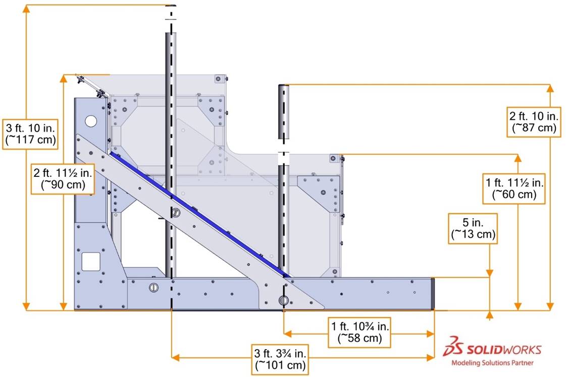
Each CONE NODE is a 1¼ in. Schedule 40
(1.66 in. (~4 cm) outer diameter) aluminum pipe with a plug installed in the
top (Caplugs
part number CCF-RT-13-1). CONE NODES are perpendicular to FIELD carpet. The
top of a CONE NODE in the middle ROW is 2 ft. 10 in. (~87 cm) above FIELD
CARPET. The top of a CONE NODE in the top ROW is 3 ft. 10 in. (~117 cm) above
FIELD carpet. The center of a middle ROW CONE NODE is 1 ft. 10¾ in. (~58 cm)
from the front face of the GRID. The center of a top ROW CONE NODE is 3 ft. 3¾
in. (~101 cm) from the front face of the GRID. A polycarbonate fin runs between
each middle ROW CONE NODE and its adjacent top ROW CONE NODE. The textured
plastic surface beneath the CONE NODES is angled ~35° from FIELD carpet.
Figure 5‑15 GRID top view dimensions
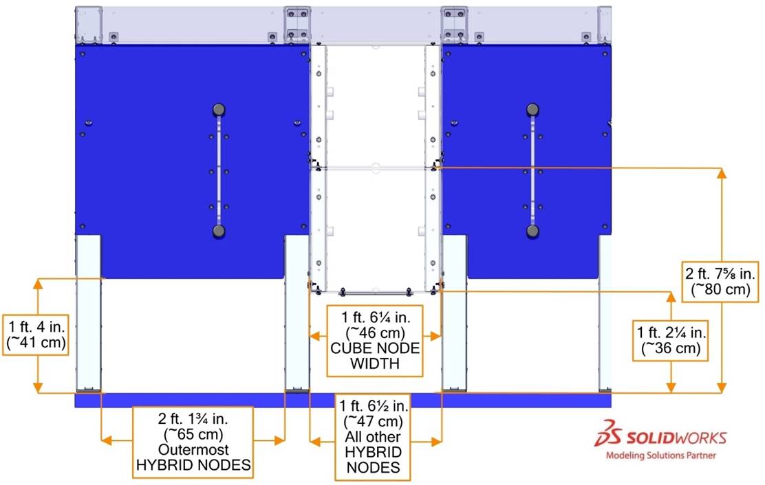
Figure 5‑16 GRID side view dimensions
A SUBSTATION is an assembly used to move
GAME PIECES from humans to ROBOTS or onto the FIELD. There are 2 types of
SUBSTATIONS in each SUBSTATION AREA: a SINGLE SUBSTATION and a DOUBLE
SUBSTATION.
Each SUBSTATION contains a PORTAL - a
three-dimensional volume through which humans transfer GAME PIECES to ROBOTS or
the FIELD.
We recognize that
some individuals may need an accommodation in order to use the SUBSTATIONS,
please see the language at the start of Section
8 Game Rules: Humans information.
Each ALLIANCE’S DOUBLE SUBSTATION is attached to and in-line with their opponent’s ALLIANCE WALL. Each
SINGLE SUBSTATION is in-line with the guardrail.
Figure 5‑17 SUBSTATIONS (click image to see field
tour video)
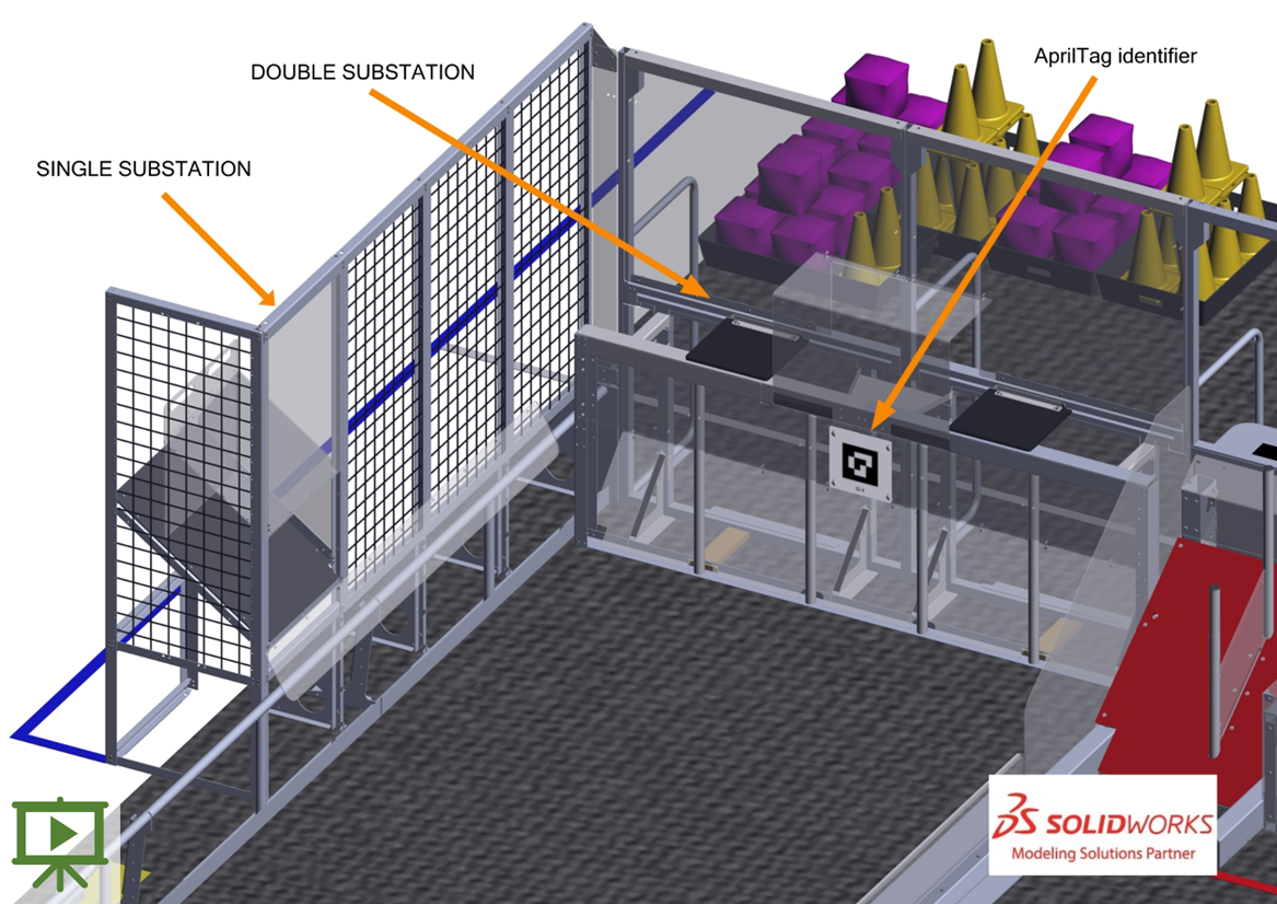
Figure 5‑18 SINGLE SUBSTATION
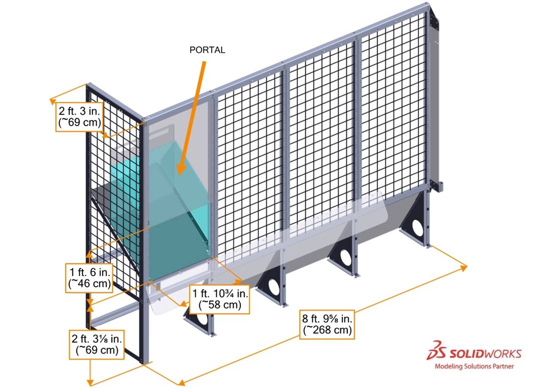
A SINGLE SUBSTATION is 8 ft. 9⅝ in. (~268 cm) wide, 6
ft. 9 ¾in. (~208 cm) tall, and 2 ft. 3 in. (~69 cm) deep. The FIELD-facing wall
of the SINGLE SUBSTATION sits 3⅛ in. (~8 cm) behind the guardrail on a traditional
FIELD and 4¼ in. (~11 cm) behind the guardrail on an AndyMark field. Each
SINGLE SUBSTATION is comprised of wire panels (Uline
H-6277BL), an attachment
point to the FIELD, and a chute assembly. The chute assembly is a tilted plastic
enclosure in which GAME PIECES enter the FIELD through a PORTAL. The FIELD-side
opening of the chute is 2 ft. 3⅛ in. (~69 cm) off the ground, 1 ft. 6 in.
(~46 cm) tall, and 1 ft. 10 ¾in. (~58 cm) wide. Each SINGLE SUBSTATION includes
a flap that retains GAME PIECES until opened by a HUMAN PLAYER. The PORTAL for
the SINGLE SUBSTATION is defined by the flap, the front face of the SINGLE
SUBSTATION, and the sides, top, and bottom plastic of the chute.
Figure 5‑19
DOUBLE SUBSTATION
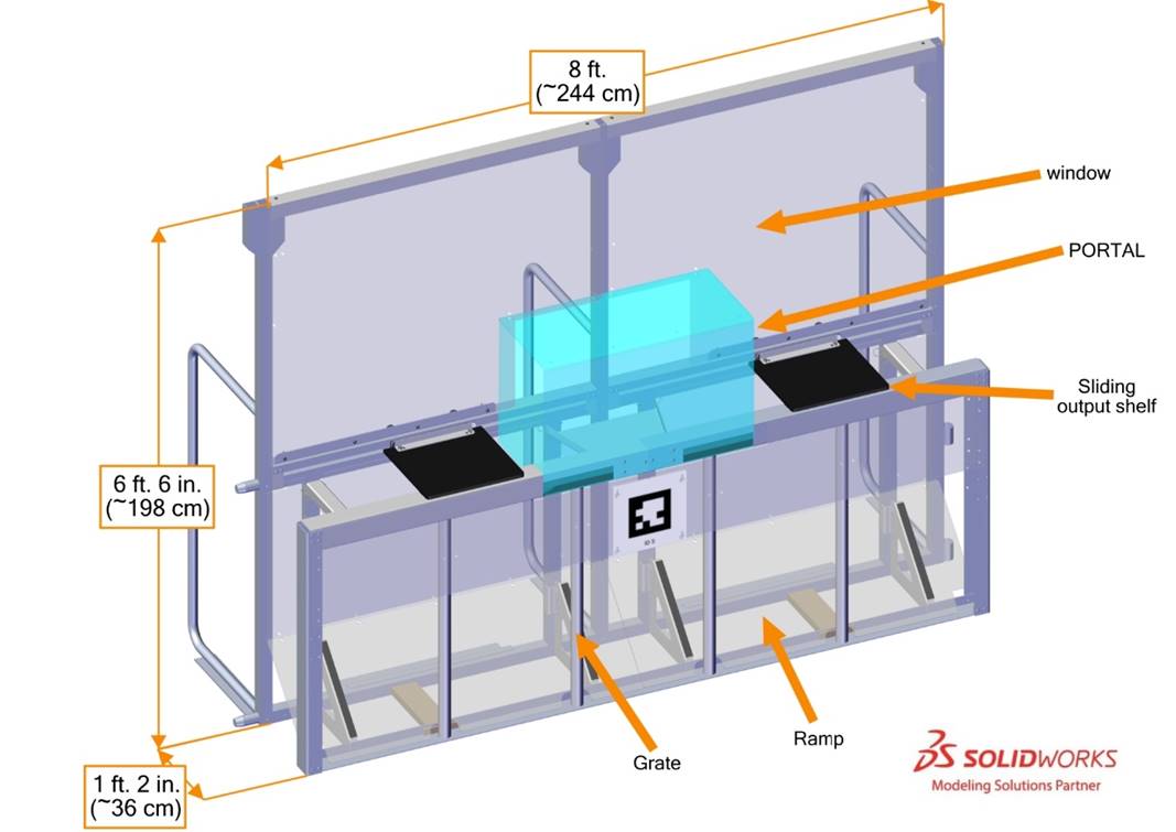
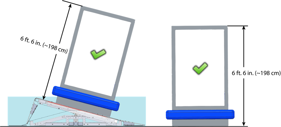
A DOUBLE SUBSTATION is a 6 ft. 6 in. (~198 cm) tall, 8 ft.
(~244 cm) wide assembly that extends 1 ft. 2 in. (~36 cm) into the FIELD. Each
DOUBLE SUBSTATION contains a grate with 5 openings, a ramp, a PORTAL, and 2
sliding output shelves.
Grate openings are defined by 1¼ in. schedule 40 aluminum
pipes which have an outer diameter of 1.66 in. (~4 cm). The distance between
pipes is 1 ft. 3 in. (~38 cm). A polycarbonate ramp spans the width of the
DOUBLE SUBSTATION, is sloped at a 45-degree angle, and extends from the grate
to the back of the DOUBLE SUBSTATION.
The DOUBLE SUBSTATION PORTAL is the volume contained between
the window and the bent polycarbonate guard, as shown in Figure 5‑19.
Sliding shelves made of ½ in. (~13 mm) thick textured HDPE
may be used to move GAME PIECES out of the PORTAL and make them accessible to
ROBOTS. Shelves are controlled by HUMAN PLAYERS using handles. The shelves are 1
ft. 2 in. (~36 cm) wide, 1 ft. 1 in. deep (~33 cm) and their top surface is 3
ft. 1⅜ in. (~95 cm) above the carpet. Each shelf can slide from the
PORTAL to an edge of the DOUBLE SUBSTATION.
Figure 5‑20
Dimensions for DOUBLE SUBSTATION
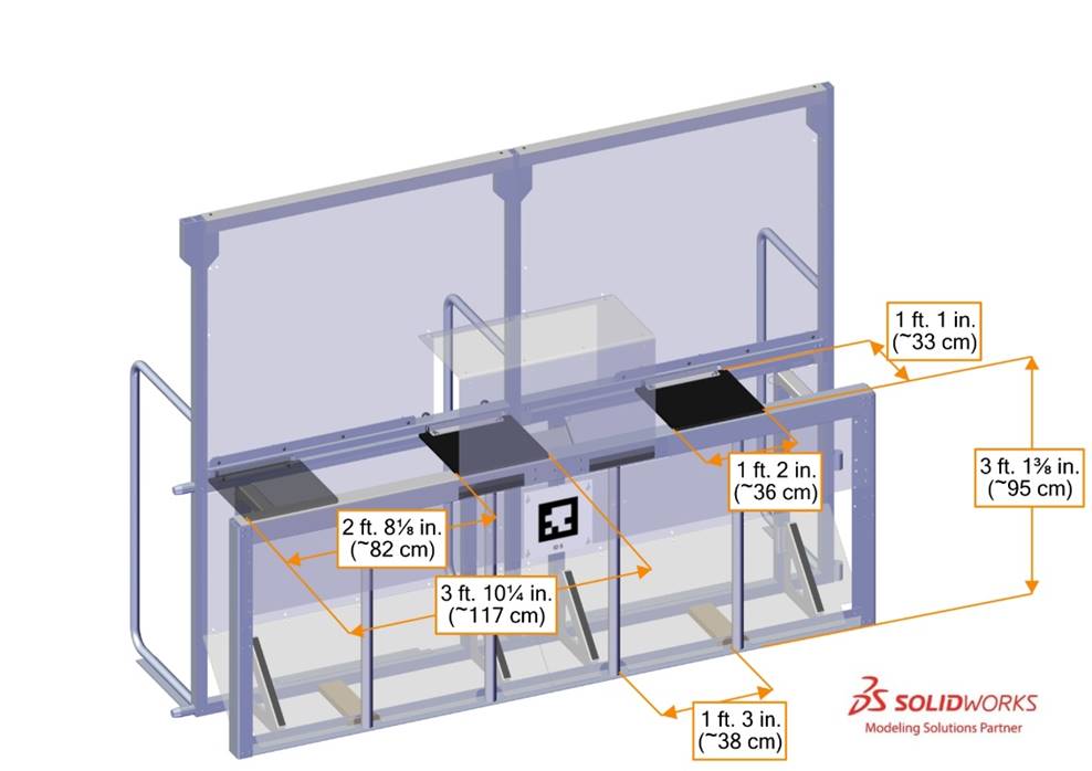
Each DOUBLE SUBSTATION is located between the guardrail and
a GRID. The distance from the edge of the PORTAL to the GRID is 2 ft. 10¼ in. +/- 1 in. (~87 cm +/- 25 mm).
The distance from the edge of the PORTAL to the guardrail is 2 ft. 10⅞
in. (~89 cm) on a traditional FIELD, or 2 ft. 10 in. (~87 cm) on an AndyMark FIELD,
as shown in Figure 5‑21.
Figure 5‑21
DOUBLE SUBSTATION distance to neighboring elements
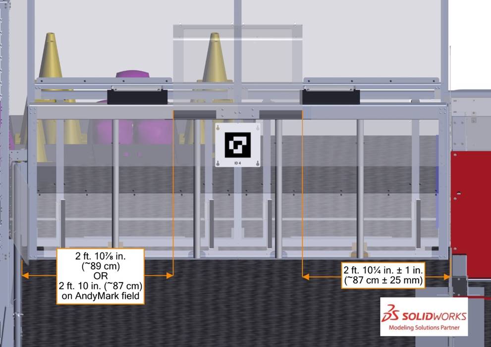
Figure 5‑22 Alliance Wall
(click image to see field tour video)
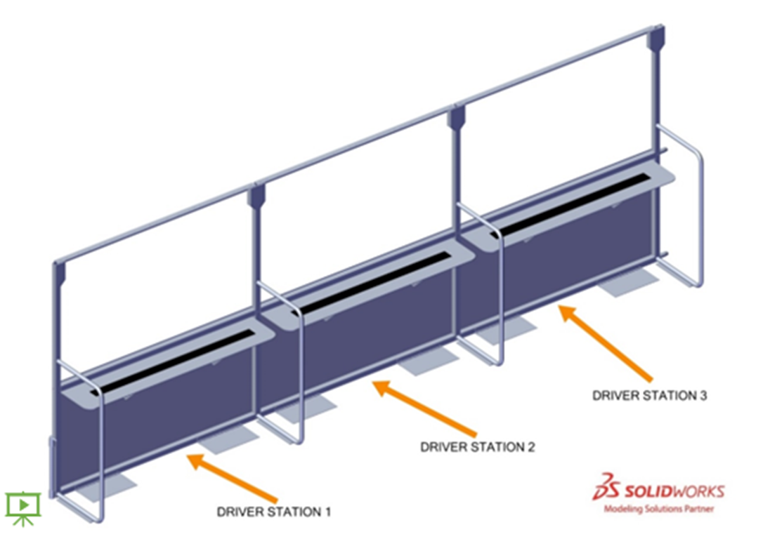
The ALLIANCE WALL separates ROBOTS from
DRIVE TEAM members in the ALLIANCE AREA.
It consists of 3 DRIVER STATIONS.
Figure 5‑23 Driver
Station dimensions
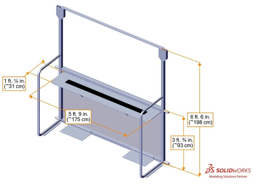
A DRIVER STATION is 1 of 3 assemblies
within an ALLIANCE WALL behind which a DRIVE TEAM operates their ROBOT.
Each Driver Station is made from a 3 ft. ¾ in.
(~93 cm) tall diamond plate base topped with a 3 ft. 6 in. (~107 cm) tall
transparent plastic sheet and a top rail. An aluminum shelf is attached to each
Driver Station to support an Operator Console. The shelf is 5 ft. 9 in. (~175 cm)
wide and 1 ft. ¼ in. (~31 cm) deep. There is a 4 ft. 6 in. (~137 cm) long by 2
in. (nominal) wide strip of hook-and-loop tape (“loop” side) along the center
of the support shelf that may be used to secure the Operator
Console to the shelf.
There may be a
ramp available at events for DRIVE TEAMS with limited mobility. It is specially
designed to allow an individual using a wheelchair to access the
DRIVER STATION shelf and/or see onto the FIELD; however, this
accommodation is available to anyone with an accessibility concern. Teams
should speak to the FTA before MATCHES begin to ensure that it is available for
each of the team’s MATCHES.
This ramp is
available at many Regional and District events. For questions please connect
with the local Program
Delivery Partner.
Each Driver Station contains
the following elements for drive teams:
- 1 Ethernet cable: attaches to the Ethernet port of the Operator Console and provides connectivity to
the Field Management System (FMS)
- 1 120VAC NEMA 5-15R power outlet (i.e. standard US outlet):
located on each Driver Station shelf and
protected by its own 2-Amp circuit breaker. It can be used to power the Operator Console. drive
teams are responsible for monitoring their power consumption as a
tripped breaker in the outlet does not constitute an Arena Fault. For some events in regions that
don’t use NEMA 5-15 shaped outlets, event organizers may install appropriate
plug adapters to be used throughout the event.
- 1 Emergency Stop (E-Stop) button: located on the left side
of the Driver Station shelf and is used to
deactivate a Robot in an emergency
- 1 team sign: displays the team number and located at the
top of each Driver Station
- 1 team LED stack: indicates Alliance
color, Robot status, E-Stop status, and is
centered at the top of each Driver Station.
The stack includes 2 identical alliance-colored robot
status LEDs above a third amber E-stop LED. LED states are as follows:
- robot status LEDs
- Solid: indicates that the Robot
is connected and enabled. This only happens during a Match.
- Blinking: indicates that either the FMS is preset for the Match and the Robot
is not connected yet, or it’s during a Match
and the corresponding Robot is Bypassed, has lost connectivity, or the E-stop
was pressed.
- Off: indicates that the Robot
is linked and Disabled prior to the
start of the Match. This light is also
off, regardless of Robot connection
status, after the Match has concluded.
- E-stop LED
- Solid: the robot is disabled due to a press of the team E-stop
button, the field E-stop button, or by
the scorekeeper via the FMS.
- Off: the robot is not disabled by the field.
·
1 string of LED nodes described in DRIVER
STATION LED Strings.
- 1 timer (in Driver Station
2 only): displays the official time remaining in the Match. It is marked with white tape along the
bottom edge.
·
FMS hardware and wiring: mostly located below the Driver Station 2 shelf
A string of LED nodes is mounted to the bottom of each Driver Station window frame. The string is used to
communicate field safety information, match state, and GRID
progress.
If the light string is all green, the field is safe for humans.
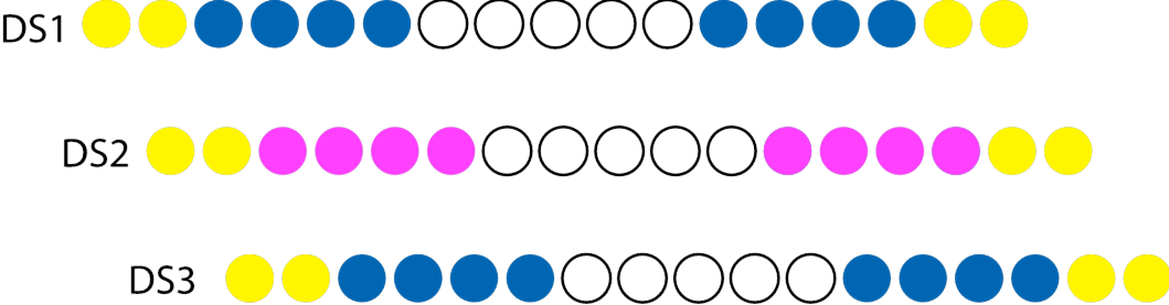
Table 5‑2 GRID light states (field
tour video)
|
Light String State
|
Criteria
|
Example
|
|
Off
|
Outside of a MATCH: FIELD is
ready
In MATCH: GAME PIECE scoring
criteria not met
|

|
|
Green
|
Head REFEREE has determined FIELD is safe for humans
|

|
|
ALLIANCE color (fills left to right when viewing from
DRIVER STATION)
|
LINK scored (1 LINK = 20% on, 2
LINKS = 40% of lights on, etc.)
|

|
|
4 outer
nodes yellow
|
DOCKED or ENGAGED scored during AUTO
|

|
|
ALLIANCE color and center 5 nodes are white
|
SUSTAINABILITY BONUS criteria
met
|

|
|
Magenta
color (fills left to right, center DRIVER STATION only)
|
COOPERTITION BONUS criteria met
|

|
|
White
|
within 3 seconds of the ending
of AUTO or TELEOP
|

|
|
Oscillating
ALLIANCE color for 3 seconds
|
Start of ENDGAME
|

|
|
5 center nodes yellow
|
Set of ALLIANCE GRIDS are
complete
|

|
Light patterns layer as ALLIANCES score throughout the
match.
Figure 5‑24 Blue ALLIANCE example light pattern –
ENGAGED in AUTO with 1 LINK achieved
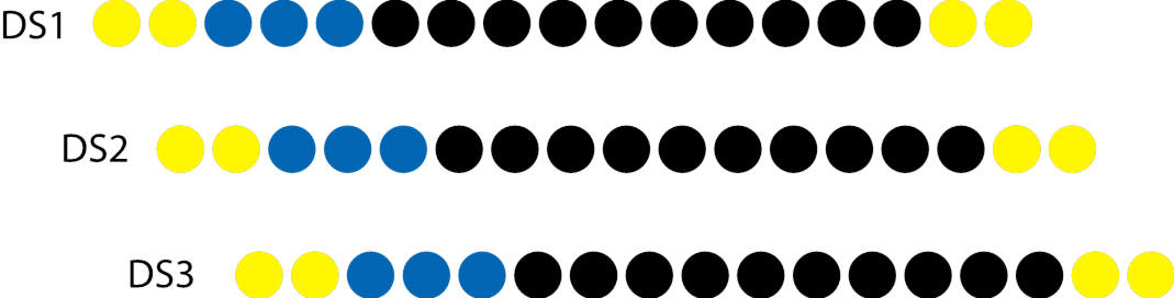
Figure 5‑25 Blue ALLIANCE example light pattern –
ENGAGED in AUTO, 4 LINKS and COOPERTITION BONUS achieved
There are 2 types of GAME PIECES: CONES
and CUBES.
Figure 5‑26 CONE
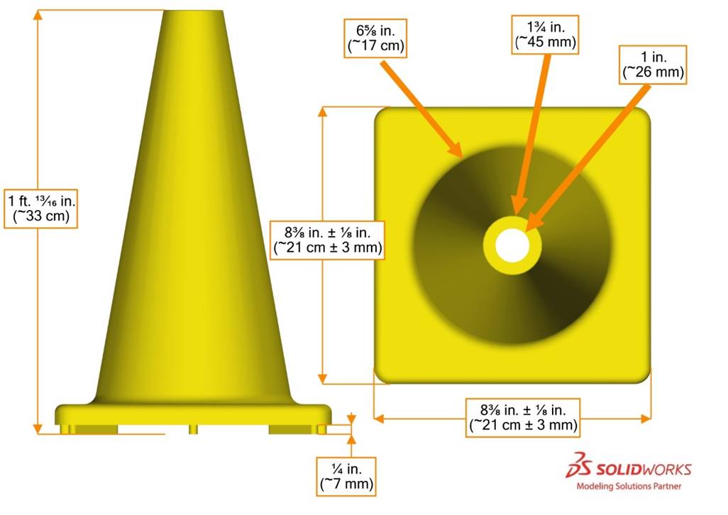
Each CONE is a yellow 1
ft. ¹³⁄₁₆
in. (~33 cm) tall rubber marker cone and weighs 1lb
7oz (~653 g). Each CONE has an 8⅜ in. (~21 cm) +/- ⅛in. (~3 mm) square
base with ¼ in. (~7 mm) tall feet. The rubber marker cone is made by Flaghouse (part
number 4158) and sold by AndyMark, part number am-4700_syc.
Figure 5‑27
CUBE
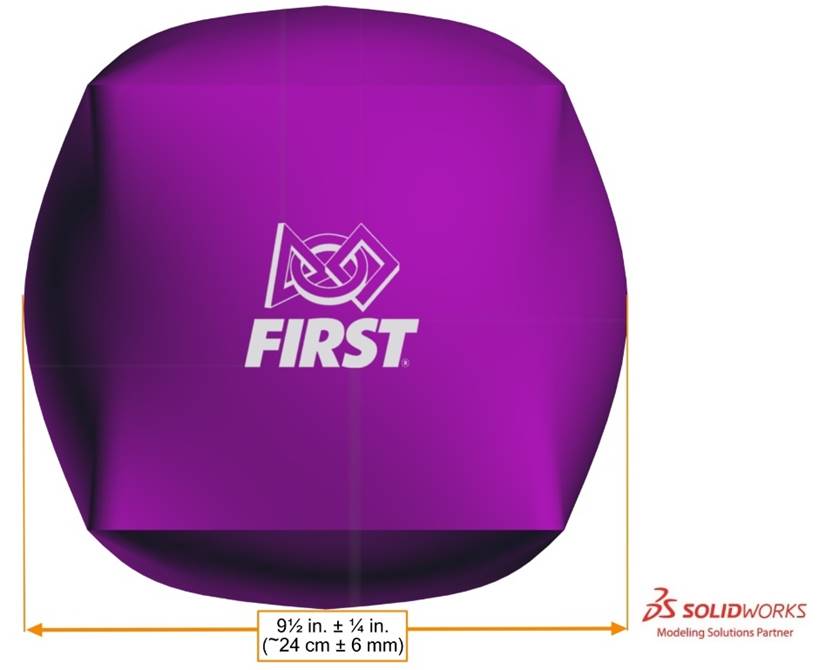
Each CUBE is made of purple PVC
fabric and is marked with a FIRST logo, as shown in Figure 5‑27. A CUBE is a cube-like shape,
inflated to 9 ½ in. (~24 cm) +/- ¼ in. (~6 mm) as measured from face to face.
A CUBE has rounded corners, may not have flat surfaces, and the length,
width, and height of the sides may not be equal dimensions. A CUBE weighs 2.5 oz (~71 g). The inflatable cube is a
modified version of a product made by Flaghouse (part number 17810) and sold by
AndyMark, part number am-4700_bpc. CUBES are
expected to experience wear during MATCHES, and small holes may be patched with
electrical tape. FIELD staff use a device to
determine a CUBE'S dimensional compliance as
shown in this video.
Note that Flaghouse part number 17810 is not identical to a
CUBE. The Flaghouse part varies in color and includes clear vinyl pouches on
all sides, whereas a CUBE does not.
GAME PIECES that begin the MATCH in the SUBSTATION AREA are
stored in containers (Uline
part number S-24135) located along the back edge each SUBSTATION AREA.
Figure 5‑28 GAME PIECE Holders
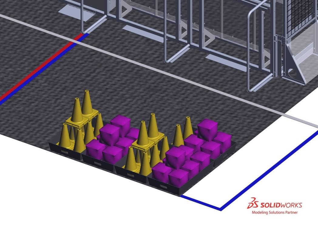
Figure 5‑29:
Vision targets on a GRID and DOUBLE SUBSTATION
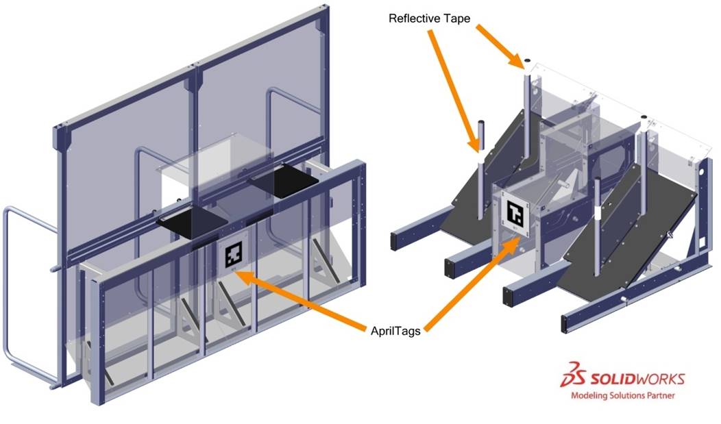
Vision
targets are located on each GRID and DOUBLE SUBSTATION. There are 2 types of
vision targets:
·
reflective
tape, and
·
AprilTags.
Samples of the reflective tape
material are included in each Kickoff Kit.
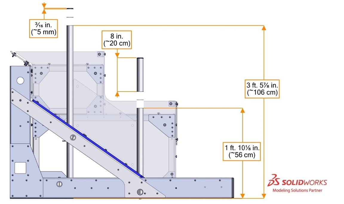
Reflective
tape vision targets are made of 2 in. (~5 cm) thick strips of 3M 973-10 Diamond Grade Flexible Prismatic
School Bus Marking Series White and are used to highlight each CONE NODE.
A 4
in. (~10 cm) tall portion of each CONE NODE is wrapped with reflective tape.
The tape is ³⁄₁₆ in. (~5 mm) from the top of Top
ROW CONE NODES and 8 in. (~20 cm) from the top of Middle ROW CONE NODES. This
results in the bottom of the targets being 3 ft. 5⅞ in. (~106 cm) and 1
ft. 10⅛ in. (~56 cm) from the FIELD carpet, as shown in Figure 5‑30. Note that the
reflective tape is likely hidden if a CONE is on the CONE NODE.
Figure 5‑30
GRID retroreflective tape
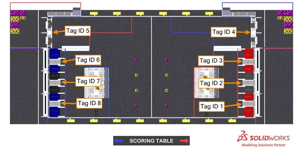
AprilTags are 8 in. (~20 cm) square targets located on the
DOUBLE SUBSTATION and GRIDS. There are 8 unique markers on the FIELD, as shown
in Figure 5‑31.
Figure 5‑31 AprilTag locations
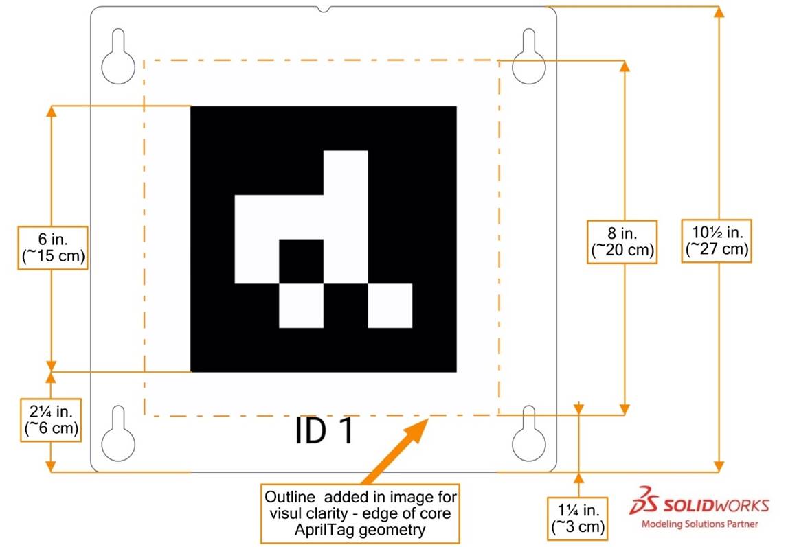
All markers are from the 16h5 tag family, IDs 1-8. AprilTags
are mounted to and centered on a 10½ in. (~27 cm) square piece of
polycarbonate. The 8 in. (~20 cm) tag is centered on the polycarbonate panel,
such that the bottom of the central black square region is 2¼ in. (~6 cm) from
the bottom of the panel, and the bottom of the 8 in. (~20 cm.) tag is located 1
¼ in. (~3 cm) from the bottom of the panel as shown in Figure 5‑32. Each
marker has an identifying text label.
AprilTags are likely to experience wear and marking during
MATCHES and are repaired with gaffers tape.
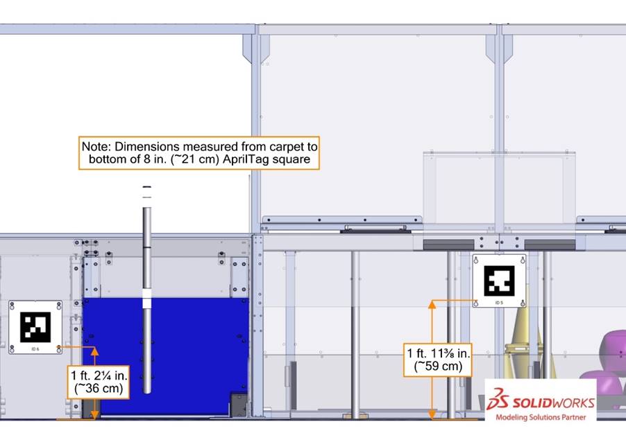
Figure 5‑32
AprilTag sizing
GRID AprilTags are centered on the width of the front face
of the middle ROW CUBE NODES and elevated such that the distance from the
carpet to the bottom of the AprilTag is 1 ft. 2¼ in. (~36 cm). Markers on the DOUBLE SUBSTATIONS are
centered on the width of the assembly and are mounted such that the distance
from the carpet to the bottom of the AprilTag is 1 ft. 11⅜ in. (~59 cm).
Figure 5‑33 AprilTag locating dimensions
For further marker locating information please refer to the 2023
ARENA Layout and Marking Diagram. For printable versions of the markers,
please refer to the 2023 Playing
Field page.
5.10
The FIELD Management System
The Field Management System
(FMS) is all electronics
responsible for sensing and controlling the FIRST Robotics Competition Field.
The FMS encompasses all Field electronics, including computers, Referee touchscreens, wireless access point, sensors,
stack lights, E-Stops, etc.
When a drive team connects
the Ethernet cable from their assigned Driver Station
to their Operator Console, the Driver Station Software on the Operator Console computer will communicate with FMS. Once connected, the open ports available are
described in Table 9‑5.
Note that Robot code cannot
be deployed while connected to the FMS.
Additional information about the FMS may be
found in the FMS Whitepaper.
Table 5‑3 Audio cues
|
Event
|
Timer Value
|
Audio Cue
|
|
Match start
|
0:15
(for Auto)
|
“Cavalry
Charge”
|
|
Auto ends
|
0:00 (for Auto)
|
“Buzzer”
|
|
Teleop begins
|
2:15
|
“3
Bells”
|
|
ENDGAME begins
|
0:30
|
“Train Whistle”
|
|
Match end
|
0:00
|
“Buzzer”
|
|
Match stopped
|
n/a
|
“Foghorn”
|

6
MATCH Play
During CHARGED UP, 2 Alliances (an Alliance
is a cooperative of up to 4 FIRST Robotics Competition teams) play Matches, set up and implemented per the details
described below.
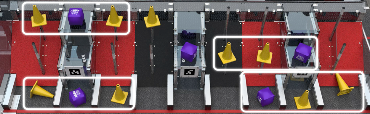
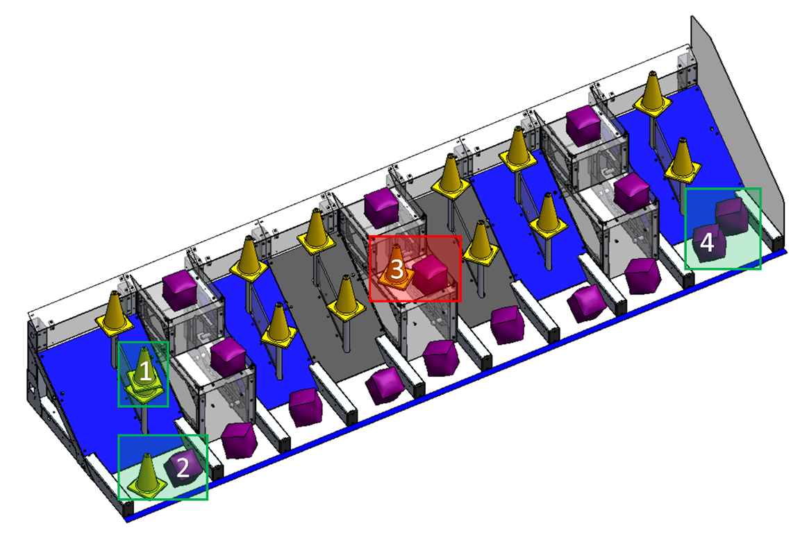
Figure
6‑1 Match setup
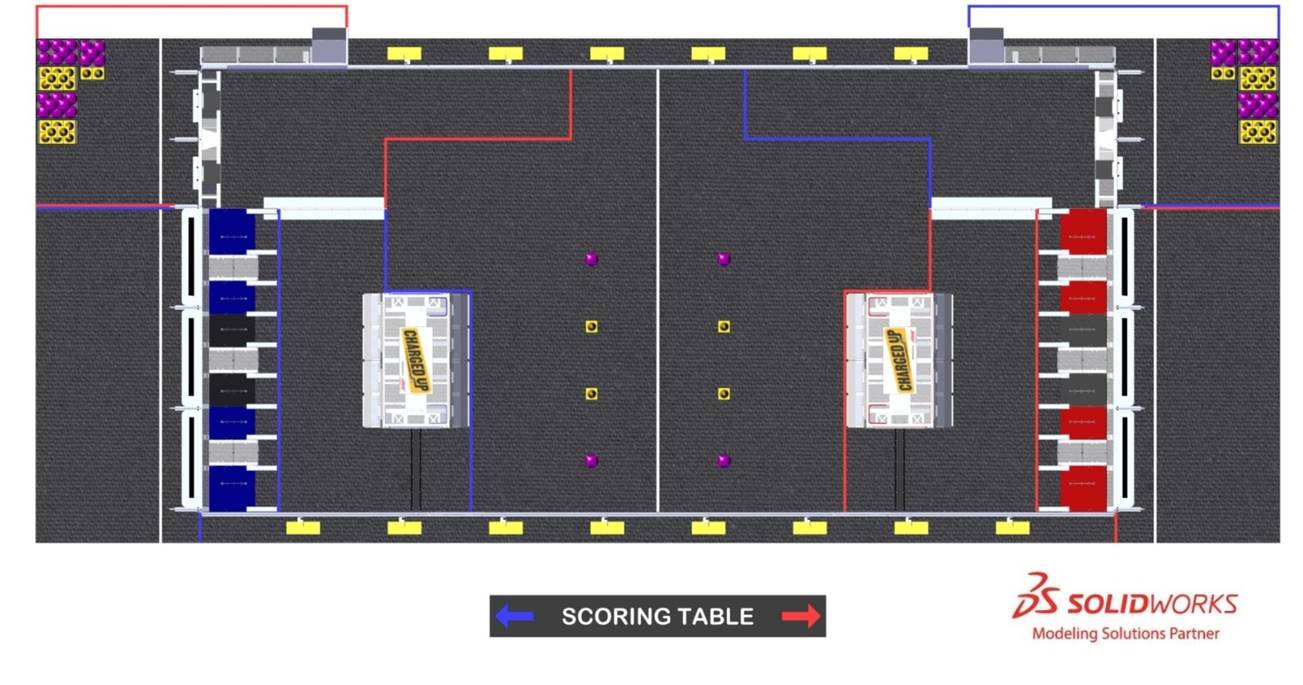
54 CONES and 44 CUBES, divided evenly between the 2 ALLIANCES,
are staged as follows:
A. each
ALLIANCE may preload 1 CONE or 1 CUBE in each ROBOT such that it is fully
supported by that ROBOT,
B. each
ALLIANCE may stage 4 GAME PIECES of their choice, 1 per any of the STAGING
MARKS between their COMMUNITY and the CENTER LINE, such that each GAME PIECE
covers or surrounds the center of its STAGING MARK (as viewed from above)
comparable to staging in Figure 6‑1,
a.
If no team decision, CUBES will be placed on the 2 outer marks and CONES
will be placed on the 2 inner marks, and
C. depending
on decisions made in A and B remaining CONES (quantity 20 to 27) and CUBES
(quantity 15 to 22) are staged in each of the corresponding ALLIANCE SUBSTATION
AREAS.
Each DRIVE TEAM stages their ROBOT such that its BUMPERS are
fully contained within their COMMUNITY and per the criteria outline in H309.
If order of placement matters to either or both ALLIANCES,
the ALLIANCE must notify the Head REFEREE during setup for that MATCH. Upon
notification, the Head REFEREE will require ALLIANCES to alternate placement of
all ROBOTS. In a Qualification MATCH, ROBOTS are placed in the following order:
1. red
DRIVER STATION 1 Robot
2. blue
DRIVER STATION 1 Robot
3. red
DRIVER STATION 2 Robot
4. blue
DRIVER STATION 2 Robot
5. red
DRIVER STATION 3 Robot
6. blue
DRIVER STATION 3 Robot
In a Playoff MATCH, a similar pattern is applied with the
lower seeded ALLIANCE placing first and alternating placement afterwards.
Humans stage for the MATCH as follows:
A. DRIVERS
and COACHES stage inside their ALLIANCE AREA and behind the STARTING LINE.
B. HUMAN
PLAYERS stage behind the STARTING LINE in either their SUBSTATION AREA or
ALLIANCE AREA.
C. TECHNICIANS stage in the event-designated area near the
FIELD.
The first phase
of each MATCH is 15 seconds long and called the Autonomous Period (AUTO). During
AUTO, ROBOTS operate without any DRIVE TEAM control or input. ROBOTS
attempt to score GAME PIECES on GRIDS, exit their ALLIANCE’S COMMUNITY,
retrieve additional GAME PIECES, and DOCK on and/or ENGAGE with their CHARGE
STATION before the end of the phase. There is a 3 second delay between AUTO and
TELEOP for scoring purposes as described in Section 6.4
Scoring.
The second phase of each MATCH is the
remaining two minutes and fifteen seconds (2:15) and called the Teleoperated
Period (TELEOP). During this phase, DRIVERS remotely operate ROBOTS to retrieve
and score GAME PIECES.
The final thirty (0:30) seconds
of the TELEOP stage is the ENDGAME, during which ROBOTS attempt to PARK, DOCK
on, and/or ENGAGE with their ALLIANCE’S CHARGE STATION or continue to score
GAME PIECES.
ALLIANCES are rewarded for accomplishing various
actions through the course of a MATCH, including demonstrating MOBILITY,
scoring GAME PIECES on GRIDS, completing LINKS, DOCKING on and/or ENGAGING with
their CHARGE STATION, PARKING, and winning or tying MATCHES.
Rewards are granted either via MATCH points or Ranking
Points (sometimes abbreviated to RP, which increase the measure used to rank
teams in the Qualification Tournament). Such actions, their criteria for
completion, and their point values are listed throughout this section.
All scores are assessed and updated throughout the Match, except as follows:
A. assessment
of CHARGE STATION scoring occurs 3 seconds
after the ARENA timer displays 0 following AUTO
B. GAME
PIECES scored in the GRID continues for up to 3
seconds after the Arena timer displays 0
following Auto.
C. assessment
of PARKING and CHARGE STATION scoring occurs 3
seconds after the ARENA timer displays 0 following TELEOP
D. GAME
PIECES scored in the GRID continues for up to 3
seconds after the Arena timer displays 0
following Teleop.
If a GAME PIECE scored in AUTO gets removed from its NODE
during TELEOP, the AUTO points are removed. If a GAME PIECE is scored in that
NODE again, the AUTO points associated with the original scored GAME PIECE are
restored.
All points are evaluated
and scored by human volunteers. Teams are encouraged to make sure that it is
obvious and unambiguous that a Robot or GAME
PIECE has met the criteria.
ALLIANCES earn points by scoring GAME PIECES in NODES on their
GRIDS. All GAME PIECES scored on the same ROW are worth equal value, as
described in Table 6‑2.
Table 6‑1 GAME PIECE Scoring Criteria
|
ROW
|
GAME PIECE
|
Scoring Criteria
|
|
Bottom
|
CONE or CUBE
|
Fully contained in GRIDS and touching
FIELD carpet, BARRIER in only 1 HYBRID NODE, and/or GAME PIECES touching
FIELD carpet and/or BARRIER in only 1 HYBRID NODE.
|
|
Middle or Top
|
CONE
|
The top of the CONE NODE is contained within the volume
defined by the conical surface of the CONE
|
|
Middle or Top
|
CUBE
|
partially or completely
(regardless of inflation state) supported by a CUBE NODE and/or by a CUBE at
least partially supported by a CUBE NODE.
|
An ALLIANCE earns 1 LINK if 3 adjacent NODES in
a ROW contains a scored GAME PIECE. A scored GAME PIECE only contributes
towards 1 LINK at a time. LINKS are assessed in a manner that optimizes the
number of LINKS awarded to an ALLIANCE.
Figure 6‑2 LINK examples
To be considered scored, a GAME PIECE may not be supported
directly or transitively by an ALLIANCE ROBOT.
If all ALLIANCE’S NODES are populated with a scored GAME
PIECE, i.e. the set of GRIDS is complete, NODES may become SUPERCHARGED. A NODE
is SUPERCHARGED if it contains more than 1 scored GAME PIECE, as defined in Table 6‑1. A GAME PIECE may only SUPERCHARGE 1 NODE.
On an incomplete set of GRIDS, only 1 GAME PIECE is counted
per NODE. On a complete set of GRIDS, additional GAME PIECES are only used to
SUPERCHARGE NODES (i.e. they do not earn ROW-specific points or contribute to
LINKS). For example, NODES 1, 2, and 4 in Figure 6‑3 are SUPERCHARGED,
NODE 3 is not SUPERCHARGED because a CONE cannot score on a CUBE NODE, and the
ALLIANCE earned 9 SUPERCHARGED NODE points.
Figure 6‑3
SUPERCHARGED NODE examples
A ROBOT earns points for its ALLIANCE
by DOCKING on or ENGAGING with their CHARGE STATION, as outlined in Table 6‑2.
A ROBOT is DOCKED if it is contacting only
the CHARGE STATION and/or other items also directly or transitively fully
supported by the CHARGE STATION.
A ROBOT is ENGAGED if both of the following criteria are
met:
A.
the CHARGE STATION is LEVEL, and
B.
all ALLIANCE ROBOTS contacting the CHARGE STATION are DOCKED.
Point values for tasks in CHARGED UP are detailed in Table 6‑2.
Table 6‑2
CHARGED UP points
An ALLIANCE can earn up to 4 Ranking Points (RP) per
Qualification MATCH, as described in Table 6‑2. There are no Ranking
Points in Playoff MATCHES.
Upon any instance of a rule violation, unless otherwise noted, 1 or more of the
penalties listed in Table 6‑3 are assessed.
Table 6‑3
Rule violations
FIRST
Robotics Competition uses 3 words in the context
of how rules and violations are assessed in deliberate ways. These words
provide general guidance to describe benchmarks to be used across the program.
It is not the intent for Referees to provide a
count during the time periods.
·
Momentary describes
rule violations that happen for fewer than approximately 3 seconds.
·
Continuous describes
rule violations that happen for more than approximately 10 seconds.
·
Repeated describes
rule violations that happen more than once within a Match.
See Section 11.2.2 YELLOW and RED
CARDS for additional details.
There are several styles of violation wording used in this
manual. Below are some example violations and a clarification of the way the
violation would be assessed. The examples shown do not represent all possible
violations, but rather a representative set of combinations.
Table 6‑4
Violation examples
|
Example
Violation
|
Expanded Interpretation
|
|
Foul
|
Upon violation, a Foul is assessed against the violating Alliance.
|
|
Tech Foul and Yellow
Card
|
Upon violation, a Tech Foul
is assessed against the violating Alliance.
After the Match, the Head Referee presents the violating team with a Yellow Card.
|
|
Foul per additional GAME PIECES.
If egregious, Yellow Card
|
Upon violation, a number of Fouls are assessed against the violating Alliance equal to the number of additional GAME PIECES beyond the permitted quantity. Additionally, if the Referees determine that the action was egregious, the Head Referee presents the violating team with a Yellow Card after the Match.
|
|
Tech Foul, plus an additional Tech Foul for every 5 seconds in which the
situation is not corrected
|
Upon violation, a Tech Foul
is assessed against the violating Alliance
and the Referee begins to count. Their count
continues until the criteria to discontinue the count are met, and for each 5
seconds within that time, an additional Tech Foul
is assessed against the violating Alliance. A
Robot in violation of this type of rule for
15 seconds receives a total of 4 Tech Fouls
(assuming no other rules were being simultaneously violated).
|
|
Red Card for the Alliance
|
After the Match, the Head Referee presents
the violating Alliance with a Red Card in the
following fashion:
a)
In a PLAYOFF Match, a single Red Card is
assessed to the Alliance.
b)
In all other scenarios, each team on the Alliance is issued a Red Card.
|
A drive team is a set of up to 5 people from the same FIRST Robotics Competition team responsible for team performance
for a specific Match. There are 4 specific
roles on a drive team which Alliances can use to assist Robots
with CHARGED UP. Only 1 of the 5 drive team
members is permitted to be a non-Student.
The intent of the
definition of drive team and drive team related rules is that, barring extenuating
circumstances, the drive team consists of
people who arrived at the event affiliated with that team and are responsible
for their team’s and Robot’s performance at the
event (this means a person may be affiliated with more than 1 team). The intent
is not to allow teams to “adopt” members of other teams for strategic advantage
for the loaning team, borrowing team, and/or their Alliance
(e.g. an Alliance Captain believes 1 of their Drivers has more experience than a Driver on their first pick, and the teams agree the first
pick team will “adopt” that Driver and make
them a member of their drive team for
Playoffs).
The definition
isn’t stricter for 2 main reasons. First, to avoid additional bureaucratic
burden on teams and event volunteers (e.g. requiring that teams submit official
rosters that Queuing must check before allowing a drive
team into the Arena). Second, to provide
space for exceptional circumstances that give teams the opportunity to display Gracious
Professionalism (e.g. a bus is delayed, a Coach
has no Drivers, and their pit neighbors agree
to help by loaning Drivers as temporary members
of the team until their bus arrives).
Table 6‑5 Drive team
roles
A STUDENT is a
person who has not completed high-school, secondary school, or the comparable
level as of September 1 prior to Kickoff.
The Technician provides teams with a technical resource
for pre-Match setup, Robot
connectivity, Operator Console troubleshooting,
and post-Match removal of the Robot. Some pre-Match
responsibilities for the Technician may
include, but are not limited to:
·
location of the Robot radio, its power connection, and understanding
of its indicator lights,
·
location of the roboRIO and
understanding of its indicator lights,
·
username and password for the Operator Console,
·
restarting the Driver Station and
Dashboard software on the Operator Console,
·
changing the bandwidth utilization
(e.g. camera resolution, frame rate, etc.),
·
changing a battery, or
·
charging pneumatics.
While the Technician may be the primary technical member of the
drive team, all members of the drive team are encouraged to have knowledge of the
basic functionality of the Robot, such as the
location and operation of the main circuit breaker, connecting and resetting
joysticks or gamepads from the Operator Console,
and removing the Robot from the Field.
game pieces that leave the Field are placed back into the Field approximately at the point of exit by Field Staff (Referees,
FIRST Technical Advisors (FTAs), or
other staff working around the Field) at the
earliest safe opportunity.
Note that Robots may not deliberately cause GAME PIECES to leave the Field
(see G401).
An Arena Fault is not called
for Matches that accidentally begin with damaged
game pieces. Damaged GAME
PIECES are not replaced until the next Arena
reset period. Drive teams should alert the Field Staff to any missing or damaged game pieces prior to the start of the Match.
Once the Match is over and the
Head Referee determines that the Field is safe for Field
Staff and drive teams, they or their
designee change the LED lights to green and drive
teams may retrieve their Robot.
In addition to the 2 minutes and 30 seconds (2:30) of game
play, each Match also has pre- and post-Match time to reset the Arena.
During Arena reset, the Arena is cleared of Robots
and Operator Consoles from the Match that just ended, Robots
and Operator Consoles for the subsequent Match are loaded into the Arena
by drive teams, and Field
Staff reset Arena elements.
7
Game Rules: ROBOTS
G101
*Dangerous Robots: not allowed. Robots
whose operation or design is dangerous or unsafe are not permitted.
Violation: If before the Match,
the offending Robot will not be allowed
to participate in the Match. If during
the Match, the offending Robot will be Disabled.
Examples include,
but are not limited to:
a. uncontrolled motion that cannot be stopped by the drive team,
b. Robot parts “flailing” outside of the Field,
c. Robots dragging their battery, and
d. Robots that consistently extend outside the Field.
G102
*Robots, stay on the Field during the Match. Robots and anything
they control, e.g. GAME PIECES, may not contact
anything outside the Field except for Momentary contact inside the PORTALS.
Violation: Disabled.
Please be
conscious of Referees and Field Staff working around the Arena who may be in close proximity to your Robot.
G103
*Keep your Bumpers low. Bumpers must be in the Bumper
Zone
(see R402) during the Match.
Violation: Foul. If Repeated or greater than Momentary, Disabled.
G104
*Keep your Bumpers together. Bumpers
may not fail such that a segment completely detaches, any corner (as defined in
R401) of a Robot’s Frame Perimeter is exposed, or the team number or Alliance color are indeterminate.
Violation: Disabled.
G105
*Keep it together. Robots may not intentionally detach or leave parts on
the Field.
Violation: Red Card.
G106
Tall Robots not allowed.
Robot height, as measured when it’s resting
normally on a flat floor, may not exceed 6 ft. 6 in. (~198 cm)) above the
carpet during the MATCH.
Violation: Foul.
This measurement
is intended to be made as if the Robot is
resting on a flat floor, not relative to the height of the Robot from the Field
carpet.
For example, a Robot that is at an angle while driving over
something may actually exceed the height limit when compared to the carpet of
the Field.
Figure 7‑1
Robot height example
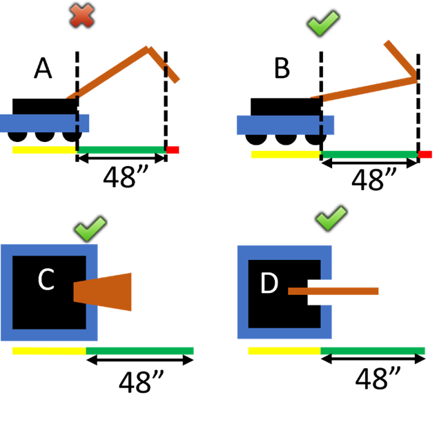
G107 Don’t overextend yourself. ROBOTS may not extend beyond
their FRAME PERIMETER in more than 48 in. (~122 cm). MOMENTARY and
inconsequential extensions beyond 48 in. (~122 cm) are an exception to this
rule.
Violation: FOUL. TECH FOUL if the over-extension scores a
GAME PIECE. If the over-extension results in the ROBOT blocking all access to a
FIELD ELEMENT, RED CARD
MOMENTARY and
inconsequential extensions include a wire or cable tie swinging out of the
FRAME PERIMETER, including while an extension is deployed.
Examples of
compliance and non-compliance of this rule are shown in Figure 7‑2.
Yellow bars
represent the limits of the Frame Perimeter and
are drawn in the same orientation of the Robot’s
Frame Perimeter. Green bars represent a
measured extension from the Frame Perimeter
that does not exceed the limit defined in this rule. Red bars represent a
measured extension from the Frame Perimeter
that exceeds the limit in this rule.
·
ROBOT A violates this rule for having
an extension that is too long
·
ROBOT B does not violate this rule
·
ROBOT C does not violate this rule
·
ROBOT D does not violate this rule
Figure 7‑2 Examples of compliance and
non-compliance of this rule
G108
Opponent’s zone, no extension. A ROBOT whose BUMPERS are intersecting the opponent’s LOADING
ZONE or COMMUNITY may not extend beyond its FRAME PERIMETER. Violations
which are both MOMENTARY and inconsequential are an exception to this rule.
Violation: FOUL or TECH FOUL if REPEATED.
Examples of MOMENTARY
and inconsequential extensions include a wire or cable tie swinging out of the FRAME
PERIMETER.
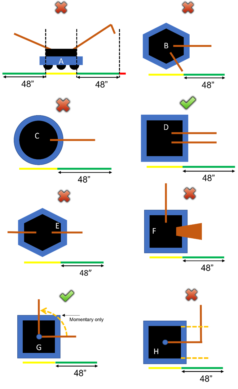
G109 Don’t extend in multiple directions. ROBOTS may not
extend beyond their FRAME PERIMETER in more than one direction (i.e. over 1
side of the ROBOT) at a time. The extension may not reach outside the
projection of that side of the FRAME PERIMETER. For the purposes of this rule,
a round or circular section of FRAME PERIMETER is considered to have an
infinite number of sides. Exceptions to this rule are:
A.
MOMENTARY and inconsequential extensions in multiple directions,
B.
A ROBOT fully contained within its LOADING ZONE or COMMUNITY, and
C.
MOMENTARY movement of a MECHANISM from 1 FRAME PERIMETER side to an
adjacent FRAME PERIMETER side.
Violation: FOUL. TECH FOUL if extending in multiple
directions scores a GAME PIECE. If extending in multiple directions results in
the ROBOT blocking all access to a FIELD ELEMENT, RED CARD
MOMENTARY and
inconsequential actions include a wire or cable tie swinging out of the FRAME
PERIMETER, including while an extension is deployed.
Examples of
compliance and non-compliance of this rule are shown in Figure 7‑3.
Yellow bars
represent the limits of the Frame Perimeter and
are drawn in the same orientation of the Robot’s
Frame Perimeter. Green bars represent a
measured extension from the Frame Perimeter
that does not exceed the limit defined in this rule. Red bars represent a
measured extension from the Frame Perimeter
that exceeds the limit in this rule.
All following
examples are legal in ROBOT’S LOADING ZONE and COMMUNITY.
·
ROBOT A violates this rule for
extending in more than one direction
·
ROBOT B violates this rule for
extending in more than one direction
·
ROBOT C violates this rule for extending
beyond an infinite number of sides and therefore any extension over an arc
extends over multiple sides
·
ROBOT D does not violate this rule
·
ROBOT E violates this rule for
extending in more than one direction
·
ROBOT F violates this rule for
extending in more than one direction
·
ROBOT G does not violate this rule as
long as the extension does not exceed the definition of MOMENTARY when
positioned over the BUMPER corner.
·
ROBOT H violates this rule for reaching
outside the projection of the FRAME PERIMETER side.
Figure 7‑3 Examples of compliance and non-compliance of this rule
G201
*Don’t expect to gain by doing
others harm. Strategies clearly aimed at forcing the opponent Alliance to violate a rule are not in the spirit of FIRST
Robotics Competition and not allowed. Rule
violations forced in this manner will not result in an assignment of a penalty
to the targeted Alliance.
Violation: Foul. If Repeated, Tech
Foul.
This rule does
not apply for strategies consistent with standard gameplay, for example:
a. a red Alliance Robot in their COMMUNITY
in the final 30 seconds of the match contacts a
blue alliance robot.
b. a blue ROBOT attempts to cut in front of the red LOADING ZONE
to reach its COMMUNITY, and a nearby red ROBOT tries to impede it via a
defensive bump and, as a result, the blue ROBOT crosses into the red LOADING ZONE.
c. a blue ROBOT attempts to enter their COMMUNITY to score a
GAME PIECE and pushes a red ROBOT just outside the blue COMMUNITY into the blue
COMMUNITY.
This rule requires
an intentional act with limited or no opportunity for the team being acted on
to avoid the penalty, such as:
d. forcing the opposing Robot to
have greater than MOMENTARY CONTROL of more than 1 GAME PIECE.
e.
a blue ALLIANCE ROBOT, already in CONTROL of a
GAME PIECE, pushing a red ALLIANCE ROBOT from fully outside and far from (i.e.
more than 4 ft.) the blue LOADING ZONE into the blue LOADING ZONE and the
REFEREE perceiving that the blue ROBOT is deliberately making the red ROBOT
violate G207.
G202 *There’s a 5-count on Pins.
Robots may not Pin
an opponent’s Robot for more than 5 seconds. A Robot is Pinning if
it is preventing the movement of an opponent Robot by contact, either direct or transitive (such
as against a Field element). A Robot is considered Pinned
until the Robots have separated by at least 6 ft.
(~183 cm) from each other, either Robot has
moved 6 ft. from where the Pin initiated, or the
PINNING ROBOT gets PINNED, whichever comes first. The Pinning Robot(s) must then wait for at least 3 seconds before
attempting to Pin the same Robot again.
Violation: Foul, plus
an additional Tech Foul for every 5
seconds in which the situation is not corrected.
A team’s desired
direction of travel is not a consideration when determining if a Robot is Pinned.
If the PINNING
ROBOT gets PINNED, the original PIN count terminates. Otherwise, if a ROBOT
re-PINS the same ROBOT before the 3 seconds referenced in the last sentence of
this rule, the REFEREE’S count resumes from the initial PIN (versus starting at
0).
G203
*Don’t collude with your
partners to shut down major parts of game play. 2 or more Robots that appear to a Referee
to be working together may neither isolate nor close off any major element of Match play.
Violation: Tech Foul,
plus an additional Tech Foul for every 5
seconds in which the situation is not corrected.
Examples of
violations of this rule include, but are not limited to:
a. shutting down access to all GAME
PIECES,
b. quarantining all opponents to a small area of the Field,
c. blocking all access to the LOADING ZONE, and
d. blocking all access to the COMMUNITY
A single Robot blocking access to a particular area of the Field is not a violation of this rule.
2 Robots independently playing defense on 2 opponent Robots is not a violation of this rule.
Note, G204, G205, and G206 are mutually exclusive. A single robot to robot
interaction which violates more than 1 of these rules results in the most
punitive penalty, and only the most punitive penalty, being assessed.
G204
*Stay out of other Robots. A robot may
not use a component outside its frame perimeter (except its bumpers)
to initiate contact with an opponent robot
inside the vertical projection of that opponent robot’s
frame perimeter.
Contact with an opponent in an opening of their bumpers
or in the space above the BUMPER opening are exceptions to this rule.
Violation: Foul.
For the purposes
of this rule, “initiate contact” requires movement towards an opponent robot.
In a collision,
it’s possible for both robots to initiate
contact.
G205
*This isn’t combat robotics.
A robot may not damage or functionally impair
an opponent robot in either of the following
ways:
A. deliberately,
as perceived by a referee.
B. regardless
of intent, by initiating contact, either directly or transitively via a GAME
PIECE CONTROLLED by the ROBOT, inside the vertical projection of an opponent robot’s frame perimeter. Contact between the robot’s bumpers or components
inside the robot’s frame perimeter and components inside an opening of an opponent’s bumpers or in the space above the BUMPER opening are exceptions
to this rule.
Damage or functional impairment
because of contact with a tipped-over opponent ROBOT, which is not perceived by
a REFEREE to be deliberate, is not a violation of this rule.
Violation: Tech foul
and yellow card. If opponent robot is unable to drive, Tech foul and red
card
FIRST Robotics Competition can be a full-contact competition and
may include rigorous game play. While this rule aims to limit severe damage to robots, teams should design their robots to be robust.
The exception in G205-B effectively means that robots with bumper
gaps are at their own risk regarding damaging contact in these areas.
Examples of
violations of this rule include, but are not limited to:
a. A robot leaves an arm
extended, spins around to change course, and unintentionally hits and damages a
component inside the frame
perimeter of a nearby opponent robot.
b. A robot, in the process of
trying to quickly reverse direction, tips up on a single pair of wheels, lands
atop an opponent robot, and damages a component inside that opponent’s frame perimeter.
c. A robot high-speed rams
and/or REPEATEDLY smashes an opponent robot and
causes damage. The referee infers that the robot was deliberately trying to the damage the
opponent’s robot.
Examples of
functionally impairing another robot include,
but are not limited to:
d. opening an opponent’s relief valve such that the opponent’s
air pressure drops and
e. powering off an opponent’s robot
(this example also clearly results in a red card because the robot
is no longer able to drive).
At the conclusion
of the match, the Head referee may elect to visually inspect a robot to confirm violations of this rule made during
a match and remove the violation if the damage
cannot be verified.
For the purposes
of this rule, “initiating contact” requires movement towards an opponent robot.
In a collision,
it’s possible for both robots to initiate contact.
"Unable to
drive" means that because of the incident, the DRIVER can no longer drive
to a desired location in a reasonable time (generally). For example, if a ROBOT
can only move in circles, or can only move extremely slowly, the ROBOT is considered
unable to drive.
G206 *Don’t tip or entangle. A robot may not deliberately, as perceived by a referee, attach to, tip, or entangle with an opponent robot.
Violation: Tech foul and yellow card. If continuous or opponent robot is unable to drive, Tech foul and red card.
Examples of violations of this rule
include, but are not limited to:
a. using a wedge-like mechanism to tip over
opponent robots,
b. making bumper-to-bumper contact with an
opponent robot that is attempting
to right itself after previously falling over and causing them to fall over
again, and
c. causing an opponent
robot to tip over by
contacting the robot after it starts to
tip if, in the judgement of the referee, that contact could have been avoided.
Tipping as an unintended consequence of
normal robot to robot interaction, as
perceived by the referee, is not a violation of this rule.
"Unable to
drive" means that because of the incident, the DRIVER can no longer drive
to a desired location in a reasonable time (generally). For example, if a ROBOT
can only move in circles, or can only move extremely slowly, the ROBOT is
considered unable to drive.
G207
Right of way. A ROBOT with any part of itself in their opponent’s LOADING
ZONE or COMMUNITY may not contact an opponent ROBOT, regardless of who
initiates contact.
Violation: Foul per
instance.
Teams should take note that they are putting themselves at
great risk for FOULS if they sit in front of or choose to enter their
opponent’s LOADING ZONE or COMMUNITY.
Figure 7‑4:
G207 Examples
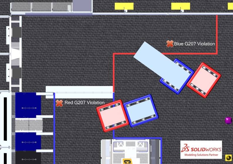
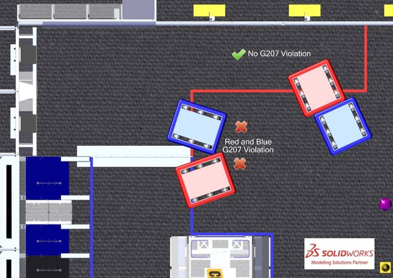
G208 Don’t climb on each other unless in the COMMUNITY. A ROBOT may not be fully supported by a partner ROBOT unless
the partner’s BUMPERS intersect its COMMUNITY.
Violation: Tech FouL per instance.
G209 During the ENDGAME, don’t touch ROBOTS touching their CHARGE STATION.
During the ENDGAME, a ROBOT may not contact, either
directly or transitively through a GAME PIECE, an opponent ROBOT contacting its
CHARGE STATION or supported by a partner contacting its CHARGE STATION,
regardless of who initiates contact. A ROBOT in contact with its CHARGE STATION
and partially in its opponent’s LOADING ZONE is not protected by this rule.
Violation: The contacted opponent
ROBOT, and any ROBOTS contacting their CHARGE STATION when the violation
occurred, and any partners it’s supporting, will be considered DOCKED and all
DOCKED ROBOTS at the end of the MATCH are considered ENGAGED.
G301 Be careful what you interact with. Robots and Operator Consoles
are prohibited from the following actions with regards to interaction with Arena elements. Items A-D exclude GAME PIECES.
A. grabbing,
B. grasping,
C.
attaching to (including the use of a vacuum or hook fastener to
anchor to the Field carpet and excluding use of
the Driver Station hook-and-loop tape, plugging
in to the provided power outlet, and plugging the provided Ethernet cable into
the Operator Console),
D.
deforming,
E. becoming
entangled with,
F.
suspending from, and
G. damaging.
Violation: Match
won’t start until the situation is corrected. If during a Match, Tech Foul.
If during a Match and Repeated or longer
than Momentary, Yellow Card. If offense is via a Robot and the Head Referee
determines that further damage is likely to occur, offending Robot will be Disabled.
Corrective action (such as eliminating sharp edges, removing the damaging Mechanism, and/or re-inspection) may be
required before the Robot will be allowed
to compete in subsequent Matches.
GAME PIECES are expected
to undergo a reasonable amount of wear and tear as they are handled by Robots, such as scratching or marking. Gouging,
popping, tearing off pieces, or routinely marking GAME
PIECES are violations of this rule.
G302 Stay on your side before TELEOP. Before TELEOP, a ROBOT
may not intersect the infinite vertical volume created by the opponent’s
ALLIANCE WALL, the ROBOT’S DOUBLE SUBSTATION, guardrails, and CENTER LINE of
the FIELD.
Violation: FOUL. If contact with an opponent ROBOT, TECH
FOUL. If contact with opponent’s CHARGE STATION, the
opponent ALLIANCE will be considered to have a successfully DOCKED and ENGAGED
ROBOT at the end of AUTO.
If an ALLIANCE
uses a GAME PIECE to prevent motion of the CHARGE STATION, G402 may also apply.
G303 Do not interfere with opponent GAME PIECES before TELEOP.
Before TELEOP, a ROBOT action may not cause GAME PIECES staged on the opposing
side of the FIELD to move from their starting locations.
Violation: TECH FOUL per moved GAME PIECE
G304 Don’t mess with the opponent’s CHARGE STATION. ROBOTS,
either directly or transitively through a GAME PIECE, may not cause or prevent
the movement of the opponent CHARGE STATION. The following are exceptions to
this rule:
A.
movement, or prevention of movement, of an opponent CHARGE STATION
because of a MOMENTARY ROBOT action resulting in minimal CHARGE STATION
movement
B. a ROBOT
forced to contact an opponent’s CHARGE STATION because of contact by an
opponent ROBOT, either directly or transitively through a GAME PIECE or other
ROBOT (e.g. a ROBOT wedged underneath the CHARGE STATION by the opposing
ALLIANCE either intentionally or accidentally).
Violation: FOUL per instance. During
the ENDGAME, any ROBOTS contacting their CHARGE STATION when the violation
occurred, and any partners it’s supporting, will be considered DOCKED and all
DOCKED ROBOTS at the end of the MATCH are considered ENGAGED.
G305 Don’t trick the sensors. Teams may not interfere with
automated scoring hardware.
Violation: RED CARD for the ALLIANCE
G306 Don’t jam the CHARGE STATION. A ROBOT may not place any
part of itself inside the CHARGE STATION assembly (i.e. within the volume
defined by its ramps and top surface, as shown in Figure 7‑5) in an
attempt to inhibit CHARGE STATION functionality.
Violation: RED CARD
Figure 7‑5
The volume inside the CHARGE STATION
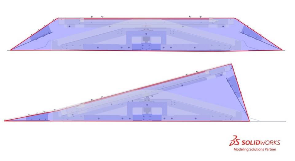
G401
*Keep GAME PIECES in bounds. Robots
may not intentionally eject GAME PIECES from
the Field (either directly or by bouncing off a
Field element or other Robot).
Violation: Foul per GAME PIECE.
G402
*GAME PIECES: use as directed. Robots may not deliberately use GAME PIECES in an attempt to ease or amplify
challenges associated with Field elements.
Violation: Tech Foul
per GAME PIECE.
Examples include, but are not limited to:
a. wedging a CUBE under the CHARGE
STATION to ease ENGAGING and
b. placing a CONE on the opponent’s CHARGE
STATION to make it harder to drive on.
G403
1 GAME PIECE at a time
(except in LOADING ZONE and COMMUNITY). ROBOTS
completely outside their LOADING ZONE or COMMUNITY may not have CONTROL of more
than 1 GAME PIECE, either directly or transitively through other objects.
A Robot is
in control of a GAME PIECE if:
A.
the GAME PIECE is fully supported by the
Robot, or
B.
the ROBOT is intentionally moving a GAME PIECE to a desired location or
in a preferred direction
Violation: Foul per
additional GAME PIECES. If egregious, Yellow Card.
Moving a GAME
PIECE to access an area of the FIELD (e.g. the CHARGE STATION) is not considered
intentionally moving to a desired location or in a preferred direction.
Egregious
examples include but are not limited to the following:
a. simultaneous control of 3 GAME PIECES
b. continuous control
of 2 or more GAME
PIECES
c. frequent Control of 2 or more GAME PIECES
(an approximate count for frequent in this context is if this rule is violated
more than 3 times in a Match)
G404 Launching GAME PIECES is only okay in the COMMUNITY. A
ROBOT may not launch GAME PIECES unless any part of the ROBOT is in its own
COMMUNITY.
Violation: TECH FOUL per GAME PIECE. REPEATED violations of
this rule are likely to escalate rapidly to YELLOW or RED CARDS.
A GAME PIECE is
considered launched if it is shot into the air, kicked across the floor, or
thrown in a forceful way.
This rule is not
intended to penalize typical movement of GAME PIECES outside an ALLIANCE’S
COMMUNITY which come to rest a short distance from the ROBOT. Examples of such
actions could be but are not limited to,
a. Running an intake in reverse causing a GAME PIECE to travel
a short distance from the ROBOT
b. A ROBOT pushing a GAME PIECE a short distance away in the
process of herding it across the FIELD
G405
Don’t mess with the opponents’ GRIDS. A
ROBOT may not move a scored GAME PIECE from an opponent's NODE.
Violation: FOUL and opponents are
awarded the SUSTAINABILITY BONUS Ranking Point.

8 Game
Rules: Humans
FIRST is committed to Equity,
Diversity, and Inclusion and as such, FIRST makes reasonable
accommodations for persons with disabilities that request accommodation. If a
participant needs an accommodation for an event, please talk to a volunteer at
the event or contact local leadership before the event so they can help ensure
the accommodation is provided.
Accommodations
are adjustments that allow all people with disabilities to access the building
and participate in the game. Accommodations are determined reasonable given
they do not create an undue hardship or cause safety concerns.
H101
*Be a good person. All teams
must be civil toward everyone and respectful of team and event equipment while
at a FIRST Robotics Competition event.
Violation: Behavior will be discussed with team or
individual. Violations of this rule are likely to escalate to yellow or Red Cards
rapidly (i.e. the threshold for egregious violations is relatively low.)
Examples of
inappropriate behavior include, but are not limited to use of offensive
language or other uncivil conduct.
Examples of
particularly contemptible behavior that is likely to result in Arena ejection include, but are not limited to, the
following:
a. assault, e.g. throwing something that hits another person
(even if unintended),
b. threat, e.g. saying something like “if you don’t reverse
that call, I’ll make you regret it,”
c. harassment, e.g. badgering someone with no new information
after a decision’s been made or a question’s been answered,
d. bullying, e.g. using body or verbal language to cause
another person to feel inadequate,
e. insulting, e.g. telling someone they don’t deserve to be on
a drive team,
f. swearing at another person (versus swearing under
one’s breath or at oneself), and
g. yelling at another person(s) in anger or frustration.
H102
*Enter only 1 Robot. Each registered FIRST
Robotics Competition team may enter only 1 Robot (or “robot,” a robot
-like assembly equipped with most of its drive base, i.e. its Major Mechanism that enables it to move around a Field) into a 2023 FIRST Robotics Competition Event.
“Entering” a Robot (or robot) into a FIRST Robotics Competition means bringing it to or using it
at the event such that it’s an aid to your team (e.g. for spare parts, judging
material, or for practice).
While “most of
its drive base” is a subjective assessment, for the purposes of this rule, an
assembly whose drive base is missing all wheels/treads, gearboxes, and
belts/chains is not considered a “robot.” If any of those Components are incorporated, the assembly is now
considered a “robot.”
This rule does
not prohibit teams from bringing in robots from other FIRST programs for
the purposes of awards presentations or pit displays.
Violation: Verbal warning. Egregious or subsequent violations
at any point during the event will be addressed by the Head Referee, the Lead Robot
INSPECTOR (LRI), and/or Event Management.
H103 *Humans, stay off the Field until green. Team members may only enter the Field if the Driver Station
LED strings are green, unless explicitly instructed by a Referee or an FTA.
Violation: Verbal warning. If
subsequent violations at any point during the event, Yellow
Card.
Egregious
violations of this rule to which H201 may apply include,
but are not limited to:
a. pushing past the Field
reset person blocking an open gate to get on the Field,
b. ignoring a warning to not go on the Field,
c. walking on to the Field
during a Match, and
d. reaching into the Field and
grabbing a Robot during a Match.
Violations of
this rule apply to the entire team, not specifically to any 1 individual. For
example, a member of Team 9999 enters the Field
prior to lights going green after Match 3, and
a different member enters the Field prior to
lights going green after Match 25. The team
receives a verbal warning for the first violation and a Yellow Card for the second.
H104
*Never step over the
guardrail. Team members may only enter or exit the Field through open gates.
Violation: Verbal warning. If subsequent
violations at any point during the event, Yellow
Card.
Teams are
encouraged to ensure that all members of their drive
team are aware of this rule. It’s easy to violate, particularly when
teams are doing their best to move on and off the Field
quickly. The violations of this rule are intended to avoid nuisance penalties,
but still enforce safety requirements around the Field.
There is the potential for injury when stepping over the guardrail.
Violations of this
rule apply to the entire team, not specifically to any 1 individual. For
example, a member of Team 9999 steps over the guardrail prior to Match 3, and a different member steps over the guardrail
prior to Match 25. The team receives a verbal
warning for the first violation and a Yellow Card
for the second.
H105
*Asking other teams to throw a
Match – not cool. A team may not encourage an Alliance, of which it is not a member, to play
beneath its ability.
NOTE: This rule is not intended to prevent
an Alliance from planning and/or executing its
own strategy in a specific Match in which all
the teams are members of the Alliance.
Violation: Behavior will be discussed with team or
individual. Violations of this rule are likely to escalate rapidly to yellow or Red Cards
and may lead to dismissal from the event (i.e. the threshold for egregious
violations is relatively low.)
Example 1: A Match is being played by Teams A, B, and C, in which
Team C is encouraged by Team D to not ENGAGE at the end of the Match, resulting in Teams A, B, and C not earning a
Ranking Point. Team D’s motivation for this behavior is to prevent Team A from
rising in the Tournament rankings and negatively affecting Team D’s ranking. Team
D has violated this rule.
Example 2: A Match is being played by Teams A, B, and C, in which
Team A is assigned to participate as a Surrogate.
Team D encourages Team A to not participate in the Match
so that Team D gains ranking position over Teams B and C. Team D has violated this
rule.
FIRST considers the action of a team influencing another team to
throw a Match, to deliberately miss Ranking
Points, etc. incompatible with FIRST values and not a strategy any team
should employ.
H106
*Letting someone coerce you in
to throwing a Match – also not cool. A team, as the result of
encouragement by a team not on their Alliance,
may not play beneath its ability.
NOTE: This rule is not intended to prevent
an Alliance from planning and/or executing its
own strategy in a specific Match in which all
the Alliance members are participants.
Violation: Behavior will be discussed with team or
individual. Violations of this rule are likely to escalate rapidly to yellow or Red Cards
and may lead to dismissal from the event (i.e. the threshold for egregious
violations is relatively low.)
Example 1: A Match is being played by Teams A, B, and C. Team D
requests Team C ignore the CHARGE STAtion at
the end of the Match, resulting in Teams A, B,
and C not being able to earn the ACTIVATION Bonus.
Team C accepts this request from Team D. Team D’s motivation for this behavior
is to prevent Team A from rising in the Tournament rankings negatively
affecting Team D’s ranking. Team C has violated this rule.
Example 2: A Match is being played by Teams A, B, and C, in which
Team A is assigned to participate as a Surrogate.
Team A accepts Team D’s request to not participate in the Match so that Team D gains ranking position over
Teams B and C. Team A has violated this rule.
FIRST considers the action of a team influencing another team to
throw a Match, to deliberately miss Ranking
Points, etc. incompatible with FIRST values and not a strategy any team
should employ.
H107
*Throwing your own MATCH is
bad. A team may not intentionally lose a MATCH or sacrifice Ranking Points
in an effort to lower their own ranking or manipulate the rankings of other
teams.
Violation: Behavior will be discussed with team or
individual. Violations of this rule are likely to escalate rapidly to yellow or Red Cards
and may lead to dismissal from the event (i.e. the threshold for egregious
violations is relatively low.)
The intent of
this rule is not to punish teams who are employing alternate strategies, but
rather to ensure that it is clear that throwing MATCHES to negatively affect
your own rankings, or to manipulate the rankings of other teams (i.e. throw a
MATCH to lower a partner's ranking, and/or increase the ranking of another team
not in the MATCH) is incompatible with FIRST values and not a
strategy any team should employ.
H108
*Don’t abuse Arena access. Team members (except Drivers, Human Players,
and Coaches) granted access to restricted areas
in and around the Arena (e.g. via Technician button, event issued Media badges, etc.)
may not assist or use signaling devices during the Match.
Exceptions will be granted for inconsequential infractions and in cases
concerning safety.
Violation: Yellow Card.
The Technician’s role is to help the team prepare the Robot so it can perform at its full potential during
a Match. The Technician,
except as described at the end of DRIVE TEAM, is not an additional Coach,
Driver, or Human
Player.
Team members in
open-access spectator seating areas are not considered to be in a restricted
area and are not prevented from assisting or using signaling devices. See E102
for related details.
H109 *Be careful what you interact with. Team
members are prohibited from the following actions with regards to interaction
with Arena elements. Temporary deformation of a
GAME PIECE (e.g.to pre-load a ROBOT) is an exception to this rule.
A.
climbing on or inside (unless instructed by FIELD staff),
B.
hanging from,
C.
deforming, and
D.
damaging.
Violation: Verbal warning. If subsequent violations at any
point during the event, YELLOW CARD.
H110 Don’t mess with GAME PIECES. Teams may not modify GAME
PIECES in any way. Temporary deformation (e.g.to pre-load a ROBOT) is an exception
to this rule.
Violation: Verbal warning. If subsequent violations at any
point during the event, YELLOW CARD.
Marking or
standing on GAME PIECES are examples of violations. Egregious violations of H109 or H110, such as cutting or
intentionally deflating GAME PIECES, are subject to H201.
H111 Don't violate rules for Ranking Points. A Team or
ALLIANCE may not collude with their OPPONENT to each purposefully violate a
rule in an attempt to earn each ALLIANCE a Ranking Point.
Violation: YELLOW CARD, and ALLIANCES are ineligible for
SUSTAINAIBLITY and ACTIVATION BONUSES.
For example, if
Team A on the blue ALLIANCE agrees with Team F on the red ALLIANCE that they
will both remove GAME PIECES from an opposing NODE, violating G405,
to incur only a FOUL and each gain a SUSTAINABILITY BONUS Ranking Point.
H201
*Egregious or exceptional
violations. Egregious behavior beyond what is listed in the rules or subsequent
violations of any rule or procedure during the event is prohibited.
In addition to rule violations explicitly
listed in this manual and witnessed by a Referee,
the Head Referee may assign a yellow or Red Card
for egregious Robot actions or team member
behavior at any time during the event. This includes violations of the event
rules found on the FIRST®
Robotics Competition District & Regional Events page.
Please see Section
11.2.2 YELLOW and RED CARDS for additional detail.
Violation: The Head Referee
may assign a yellow or a Red Card.
The intent of
this rule is to provide the Head Referees the
flexibility necessary to keep the event running smoothly, as well as keep the
safety of all the participants as the highest priority. There are certain
behaviors that automatically result in a yellow or Red Card
because this behavior puts the FIRST community at risk. Those behaviors
include, but are not limited to the list below:
a.
inappropriate behavior as outlined in the blue
box of H101,
b. jumping over the guardrail,
c. behaviors listed in the blue box in H103,
d. Pinning in excess of 15 seconds,
e.
exploiting the 3-second window after a MATCH described
in Section 6.4 Scoring to avoid rule violations (e.g. triggering an
over-extension that enables GRID points or using a ROBOT’S residual energy to
impact an opponent ROBOT on their CHARGE STATION),
f. moving a scored GAME PIECE from an opponent’s complete set
of GRIDS.
The Head Referee may assign a yellow
or Red Card for a single instance of a rule
violation such as the examples given in items a-e above, or for multiple
instances of any single rule violation. Teams should be aware that any rule in
this manual could escalate to a yellow or Red Card. The Head Referee
has final authority on all rules and violations at an event.
H202
*1 student, 1 Head REFEREE. A team may only address the Head
REFEREE with 1 STUDENT. The STUDENT may not be accompanied by more than 1
silent observer.
Violation: The Head Referee
will not address additional, non-compliant team members or peripheral
conversations.
Please see Section 11.2 Head REFEREE and FTA Interaction for
more information about process and expectations. Note that some events may
restrict ARENA access to members of the DRIVE TEAM.
If a Head REFEREE
(or any other Event staff) feels they are being recorded without their consent,
they may choose to stop participating in the conversation.
H301 *Be prompt. DRIVE
TEAMS may not cause significant delays to the start of their MATCH. Causing
a significant delay requires both of the following to be true:
A. The
expected MATCH start time has passed, and
Event volunteers
communicate schedule delays with teams to the best of their ability. The Pit
Display (which is typically located near the Pit Administration desk) shows any
event timing delay. Announcements on the FIELD and in the pits also provide information
on delays, and any team uncertain of when to queue for a MATCH should communicate with queuing volunteers.
During
Qualification MATCHES, the expected start time of the MATCH is the time
indicated on the MATCH schedule or ~4 minutes from the end of the previous
MATCH (which is reflected on the schedule on the Pit Display), whichever is
later.
During Playoff
MATCHES, the expected start time of the MATCH is the time indicated on the
MATCH schedule or 15 minutes from either ALLIANCE’S previous MATCH, whichever
is later.
B. The DRIVE TEAM has access to the FIELD
and is neither MATCH ready nor making a good faith effort, as perceived by the
Head REFEREE, to quickly become MATCH ready.
Teams that have
violated H305 or have 1
DRIVE TEAM member present and have informed event staff that their ROBOT will
not be participating in the MATCH are considered MATCH ready and not in
violation of this rule.
Violation: Verbal warning, or if a subsequent violation
within the tournament phase (i.e. Qualifications or Playoffs), TECH FOUL
applied to their upcoming MATCH. If the DRIVE TEAM is not MATCH ready within 2
minutes of the verbal warning/TECH FOUL and the Head REFEREE perceives no good
faith effort by the DRIVE TEAM to quickly become MATCH ready, DISABLED.
The intent of this
rule is to provide an equitable amount of time for both ALLIANCES to prepare
for each MATCH and give DRIVE TEAMS grace given extenuating circumstances that
causes them to be late.
Once a verbal
warning/TECH FOUL is issued, the Head REFEREE starts a 2-minute timer and makes
a good faith effort to share the timer’s status with the delaying DRIVE TEAM.
Being “MATCH ready”
requires that the ROBOT is on the FIELD, in its STARTING CONFIGURATION, and turned
on. Additionally, the DRIVE TEAM members must be in their starting positions.
In general, good
faith efforts to quickly become MATCH ready are entirely for the purposes of
transitioning the ROBOT into a MATCH ready state (i.e. not attempts to
significantly alter a ROBOT’s capabilities.) Examples of good faith efforts to quickly
become MATCH ready include but are not limited to:
a.
walking safely towards the FIELD with a ROBOT
that a team is not actively modifying,
b.
applying quick fixes such as tape or cable
ties to make the ROBOT compliant with STARTING CONFIGURATION requirements,
c.
waiting for an OPERATOR CONSOLE computer to
boot, and
d.
working with FIELD STAFF to get the ROBOT
connected to the FIELD.
Examples that are
not considered good faith efforts to quickly become MATCH ready include but are
not limited to:
e.
a ROBOT not moving to the FIELD,
f.
a ROBOT moving to the FIELD but being actively
modified while doing so,
g.
a DRIVE TEAM member remaining on the FIELD
once a MATCH is ready to begin (indicated by the green LEDs having turned off),
h.
installing BUMPERS, charging pneumatic
systems, or any other ROBOT maintenance not considered a quick fix as described
in item b above once on the FIELD, and
i.
time-consuming use of alignment devices that
are external to the ROBOT (e.g. a DRIVE TEAM could bring and use a measuring
tape, as long as there is no delay to the MATCH by doing so)
There are no
rules that prohibit use of hand tools (including battery operated tools) while
setting up ROBOTS from the FIELD, provided they do not cause significant delay
or cause safety concerns.
H302
*Teams may not enable their Robots on the Field. Teams may not
tether to the Robot while on the Field except in special circumstances (e.g. after
Opening Ceremonies, before an immediate Match
replay, etc.) and with the express permission from the FTA or a Referee.
Violation: Yellow Card
Teams are
encouraged to consider this rule when developing their robots.
FMS will not enable
Robots after the conclusion of the Match.
Tethering
includes any wired or wireless connection used to electrically energize and/or
control elements on the Robot. The safety of
teams and volunteers in close proximity to Robots
and Arena elements on the Field is of the utmost importance, therefore Robots or Robot Components may not be enabled in any way on the Field before or after the Match.
Robots need to be
safely transported off the Field and back to
the pits after the Match, and there may be
bystanders, doorways, or height restrictions along the route.
H303
*You can’t bring/use anything
you want. The only equipment that may be brought to the Arena and used by drive
teams during a Match is listed below.
Regardless of if equipment fits criteria below, it may not be employed in a way
that breaks any other rules, introduces a safety hazard, blocks visibility for Field Staff or audience members, or jams or
interferes with the remote sensing capabilities of another team or the Field.
A. the Operator Console,
B. non-powered
signaling devices,
C. reasonable
decorative items,
D. special
clothing and/or equipment required due to a disability,
E. devices
used solely for planning, tracking, and communicating strategy within the same
designated area (e.g. ALLIANCE AREA),
F. devices
used solely to record gameplay, and
G. non-powered
Personal Protective Equipment (examples include, but aren’t limited to, gloves,
eye protection, and hearing protection)
Items brought to the Arena under allowances B-G must meet all following conditions:
I.
do not connect or attach to the Operator
Console, Field, or Arena,
II.
do not connect or attach to another Alliance
member (other than items in category G),
III.
do not communicate with anything or anyone outside of the Arena,
IV.
do not communicate with the Technician,
V.
do not include any form of enabled wireless electronic communication
with the exception of medically required equipment, and
VI.
do not in any way affect the outcome of a Match,
other than by allowing the DRIVE TEAM to
a. plan
or track strategy for the purposes of communication of that strategy to other Alliance members or
b. use
items allowed per B to communicate with the Robot.
Violation: Match will
not start until situation remedied. If discovered or used inappropriately
during a Match, Yellow Card.
Examples of
equipment that may be considered a safety hazard in the confined space of the Alliance Area include, but are not limited to, a step
stool or a large signaling device.
Examples of
remote sensing capabilities include, but are not limited to, vision systems,
acoustic range finders, sonars, and infrared proximity sensors.
Use of imagery
that, to a reasonably astute observer, mimics the Vision Targets employed on
the Field is a violation of this rule.
Examples of
wireless communication include, but are not limited to, radios, walkie-talkies,
cell phones, Bluetooth communications, and Wi-Fi.
H304
*By invitation only.
Only drive teams for the current Match are allowed in their respective Alliance Areas and
SUBSTATION AREAS.
Violation: Match won’t
start until the situation is corrected.
H305 *Show up to your Matches. Upon each team’s Robot
passing initial, complete inspection, the team must send at least 1 member of
its drive team to the Arena
and participate in each of the team’s assigned Qualification and Playoff Matches.
Violation: Red Card.
Figure 8‑1
Match participation flowchart
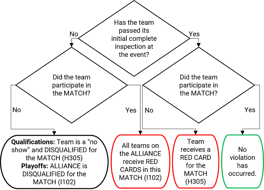
The team should
inform the lead team queuer if the team’s Robot
is not able to participate.
H306
*Identify yourself. Drive teams must wear proper identification while in
the Arena. Proper identification consists of:
A.
all drive team members wearing their
designated buttons above the waist in a clear visible location at all times
while in the Arena
B.
the Coach wearing the “Coach” button
C.
the Drivers and Human Players each wearing a “drive team” button
D.
the Technician wearing the “Technician” button
E.
during a Playoff Match, the Alliance Captain clearly displaying the designated Alliance Captain identifier (e.g. hat or armband)
Violation: Match won’t
start until the situation is corrected. Those not displaying identification
must leave the Arena.
H307 *Plug in to/be in your Driver Station. The Operator Console
must be used in the Driver Station to which the
team is assigned, as indicated on the team sign.
Violation: Match
won’t start until the situation is corrected. If during a Match, Disabled.
An intent of this
rule is to prevent unsafe situations where long tethers to Operator Console devices increase tripping hazards as
the operator moves about the Alliance Area. In
the interest of avoiding nuisance penalties associated with a DRIVE TEAM member
stepping outside of a prescribed area, we
prefer to offer a general guideline as to what it means to use the Operator Console in the Alliance
Area. Provided the Drive Team member is
within close proximity of their Driver Station,
there will be no repercussions. However, a Drive Team member located more than
approximately half a Driver Station width away
from their own Driver Station while using their
operator console is likely violating this rule.
H308
*Don’t bang on the glass.
Team members may never strike or hit the Driver
Station plastic windows.
Violation: Verbal warning. If subsequent violations in more
than 1 Match, Yellow
Card.
H309
Know your Robot setup. When
placed on the Field for a Match, each Robot
must be:
A. in
compliance with all Robot rules, i.e. has
passed inspection (for exceptions regarding Practice Matches,
see Section 10 Inspection & Eligibility Rules),
B.
the only team-provided item left on the Field
by the drive team,
C.
confined to its Starting Configuration (reference
R102 and R104),
D. positioned
such that it is fully contained within its COMMUNITY
E.
not in contact with the CHARGE STATION
F.
fully supported by FIELD carpet, gaffers tape, and/or cable protector, and
G.
fully and solely supporting not more than 1 GAME
PIECE (as described in Section 6.1 Setup).
Violation: If fix is a quick remedy, the Match won’t start until all requirements are
met. If it is not a quick remedy, the offending Robot
will be Disabled and, at the discretion
of the Head Referee, must be
re-inspected.
If a Robot is Bypassed
prior to the start of the Match, the drive team may not remove the Robot from the Field
without permission from the Head Referee or the
FTA.
H310 Know your drive team positions. Prior to the start of the Match, drive team
members must be positioned as follows:
A.
Drivers: inside their Alliance Area and behind the Starting Line,
B.
Coaches: inside their Alliance Area and behind the Starting Line, and
C.
Human Players:
a. at
least one Human Player in their SUBSTATION AREA
and behind the Starting Line,
b. any remaining
Human Players: inside their Alliance Area and behind the Starting Line, and
D.
Technicians: in the event-designated
area near the Field.
Violation: Match
won’t start until the situation is corrected.
H311
Leave the GAME PIECES alone. Prior to the start of the Match, Human Players may not rearrange the GAME
PIECES within the SUBSTATION AREA.
Violation: Match
won’t start until the situation is corrected.
H312
Leave promptly. DRIVE TEAMS may
not cause significant or multiple delays to the start of a subsequent MATCH,
scheduled break content, or other FIELD activities.
Violation: Verbal warning. If subsequent violations at any
point during the event, YELLOW CARD.
H401 *Behind the lines. During AUTO, DRIVE TEAM
members in ALLIANCE AREAS and HUMAN PLAYERS in their SUBSTATION AREAS may not
contact anything in front of the STARTING LINES, unless for personal or
equipment safety or granted permission by a Head Referee
or FTA.
Violation: Foul.
Pointing,
gesturing, or otherwise extending across the Starting
Line such that contact is not made with carpet or other Arena elements is not a violation of this rule.
An example of an
exception for equipment safety is if an Operator
Console starts to fall from, or has already fallen off of, the Driver Station shelf. In that circumstance, drive team members may step forward to catch it or
pick it up off the ground and return it to the shelf.
H402
*Disconnect or set down
controllers. Prior to the start of the Match,
any control devices worn or held by Human Players
and/or Drivers must be disconnected from the Operator Console.
Violation: Match
won’t start until the situation is corrected.
For the purposes
of FIRST Robotics Competition, any device
connected to the Operator Console is considered
a control device because Referees are not
expected to differentiate between devices that can or cannot control the Robot.
H403
*Let the Robot do its thing. During Auto,
drive teams may not directly or indirectly
interact with Robots or Operator Consoles unless for personal safety, Operator Console safety, or pressing an E-Stop.
Violation: Foul and Yellow Card
H501
*Coaches and other teams: hands off the controls. A Robot shall be operated only by the Drivers and/or Human Players
of that team.
Violation: Disabled.
Exceptions may be
made before a Match for major conflicts, e.g.
religious holidays, major testing, transportations issues, etc.
H502
*No wandering. DRIVE TEAMS may not
contact anything outside the area in which they started the Match (i.e. the Alliance
Area, the SUBSTATION Area, or the
designated TECHNICIAN space). Exceptions are
granted for a HUMAN PLAYER whose feet are partially outside the SUBSTATION AREA
(but not in the opponent ALLIANCE AREA), in cases concerning safety, and for
actions that are inadvertent, Momentary, and
inconsequential.
Violation: Foul.
H503 *Coaches, GAME
PIECES are off limits. Coaches may not touch GAME
PIECES, unless for safety purposes.
Violation: Foul
per GAME PIECE.
H504
GAME PIECES through PORTALS only. GAME
PIECES may only be introduced to the Field
A. by a Human Player,
B. through a PORTAL, and
C. during TELEOP.
Violation: Foul per GAME
PIECES.
H505
Drive Teams, watch your reach. Drive TeamS
may not extend any body part into the SINGLE SUBSTATION PORTAL for a
greater-than-MOMENTARY period of time.
Violation: Foul.
H506
Drive Teams, avoid ROBOTS. A DRIVE TEAM member may neither
A.
extend any body part into a PORTAL while any part of a ROBOT is in that
PORTAL nor
B.
contact a GAME PIECE in contact with a ROBOT.
Violation: Verbal warning. If subsequent violations at any
point during the event, YELLOW CARD.
The rules listed below explicitly address legal parts and
materials and how those parts and materials may be used on a CHARGED UP Robot. A Robot is an electromechanical assembly built by the FIRST Robotics Competition team to play the current season’s
game and includes all the basic systems required to be an active participant in
the game –power, communications, control, Bumpers,
and movement about the Field. A Bumper is a protective assembly designed to attach to
the exterior of the ROBOT and constructed as specified in Section 9.4 BUMPER Rules.
There are many reasons for the structure of the rules,
including safety, reliability, parity, creation of a reasonable design
challenge, adherence to professional standards, impact on the competition, and
compatibility with the Kit of Parts (KOP).
The KOP is the collection of items
listed on the current season’s Kickoff Kit Checklists, distributed to the team
via FIRST Choice in the current season, or paid for completely (except
shipping) with a Product Donation Voucher (PDV) from the current season.
Another intent of these rules is to have all energy sources
and active actuation systems on the Robot (e.g.
batteries, compressors, motors, servos, cylinders, and their controllers) drawn
from a well-defined set of options. This is to ensure that all teams have
access to the same actuation resources and that the INSPECTORS are able to accurately and efficiently assess the legality of a given
part.
Robots are made up of Components and Mechanisms.
A Component is any part in
its most basic configuration, which cannot be disassembled without damaging or
destroying the part or altering its fundamental function. A Mechanism is an assembly of Components that provide specific functionality on the
Robot. A Mechanism
can be disassembled (and then reassembled) into individual Components without damage to the parts.
Many rules in this section reference
Commercial-Off-The-Shelf (COTS) items. A COTS item must be a standard (i.e. not
custom order) part commonly available from a Vendor
for all teams for purchase. To be a COTS
item, the Component or Mechanism must be in an unaltered, unmodified state
(with the exception of installation or modification of any software). Items
that are no longer commercially available but are functionally equivalent to
the original condition as delivered from the Vendor
are considered COTS and may be used.
Example 1: A team
orders 2 Robot grippers from RoboHands Corp.
and receives both items. They put 1 in their storeroom and plan to use it
later. Into the other, they drill “lightening holes” to reduce weight. The first
gripper is still classified as a COTS item, but
the second gripper is now a Fabricated Item, as
it has been modified.
Example 2: A team
obtains openly available blueprints of a drive module commonly available from
Wheels-R-Us Inc. and has local machine shop “We-Make-It, Inc.” manufacture a
copy of the part for them. The produced part is not a COTS
item, because it is not commonly carried as part of the standard stock of
We-Make-It, Inc.
Example 3: A team
obtains openly available design drawings from a professional publication during
the pre-season and uses them to fabricate a gearbox for their Robot during the build period following Kickoff. The
design drawings are considered a COTS item and
may be used as “raw material” to fabricate the gearbox. The finished gearbox
itself would be a Fabricated Item, and not a COTS item.
Example 4: A COTS part that has non-functional label markings
added would still be considered a COTS part,
but a COTS part that has device-specific
mounting holes added is a Fabricated Item.
Example 5: A team
has a COTS single-board processor version 1.0,
which can no longer be purchased. Only the COTS
single-board processor version 2.0 may be purchased. If the COTS single-board processor version 1.0 is
functionally equivalent to its original condition, it may be used.
Example 6: A team
has a COTS gearbox which has been discontinued.
If the COTS gearbox is functionally equivalent
to its original condition, it may be used.
A Vendor is a
legitimate business source for COTS items that
satisfies all the following criteria:
A.
has a Federal Tax Identification number. In cases where the Vendor is outside of the United States, they must
possess an equivalent form of registration or license with the government of
their home nation that establishes and validates their status as a legitimate
business licensed to operate within that country.
B.
is not a “wholly owned subsidiary” of a FIRST Robotics Competition team or collection of teams. While
there may be some individuals affiliated with both a team and the Vendor, the business and activities of the team and Vendor must be completely separable.
C.
should maintain sufficient stock or production capability so they are
able to ship any general (i.e., non-FIRST unique) product within 5
business days of receiving a valid purchase request. It is recognized that
certain unusual circumstances (such as such as a global supply chain disruption
and/or 1,000 FIRST teams all ordering the same part at once from the
same Vendor) may cause atypical delays in shipping
due to backorders for even the largest Vendors.
Such delays due to higher-than-normal order rates are excused. This criterion
may not apply to custom-built items from a source that is both a VENDOR and a
fabricator.
For example, a Vendor may sell flexible belting that the team wishes
to procure to use as treads on their drive system. The Vendor cuts the belting to a custom length from
standard shelf stock that is typically available, welds it into a loop to make
a tread, and ships it to a team. The fabrication of the tread takes the Vendor 2 weeks. This would be considered a Fabricated Item, and the 2-week ship time is
acceptable. Alternately, the team may decide to fabricate the treads
themselves. To satisfy this criterion, the Vendor
would just have to ship a length of belting from shelf stock (i.e. a COTS item) to the team within 5 business days and
leave the welding of the cuts to the team.
D.
makes their products available to all FIRST Robotics Competition teams. A Vendor
must not limit supply or make a product available to just a limited number of FIRST
Robotics Competition teams.
The intent of
this definition is to be as inclusive as possible to permit access to all
legitimate sources, while preventing ad hoc organizations from providing
special-purpose products to a limited subset of teams in an attempt to
circumvent the cost accounting rules.
FIRST desires to permit teams to have the broadest choice of
legitimate sources possible, and to obtain COTS
items from the sources that provide them with the best prices and level of
service available. Teams also need to protect against long delays in
availability of parts that will impact their ability to complete their Robot. The build season is brief, so the Vendor must be able to get their product,
particularly FIRST unique items, to a team in a timely manner.
Ideally, chosen Vendors should have national distributors (e.g. Home
Depot, Lowes, MSC, McMaster-Carr, etc.). Remember, FIRST Robotics Competition events are not always near home –
when parts fail, local access to replacement materials is often critical.
A Fabricated Item is any Component or Mechanism that has been altered, built, cast,
constructed, concocted, created, cut, heat treated, machined, manufactured,
modified, painted, produced, surface coated, or conjured partially or
completely into the final form in which it will be used on the Robot.
Note that it is
possible for an item (typically raw materials) to be neither COTS nor a Fabricated Item.
For example, a 20 ft. (~610 cm) length of aluminum which has been cut into 5
ft. (~152 cm) pieces by the team for storage or transport is neither COTS (it’s not in the state received from the Vendor), nor a Fabricated
Item (the cuts were not made to advance the part towards its final form
on the Robot).
Teams may be asked to provide documentation proving legality
of non-CHARGED UP KOP items during inspection
where a rule specifies limits for a legal part (e.g. pneumatic items, current
limits, COTS electronics, etc.).
Some of these rules make use of English unit requirements
for parts. If your team has a question about a metric-equivalent part’s
legality, please e-mail your question to the FIRST Robotics Competition
Kit of Parts team at frcparts@firstinspires.org
for an official ruling. To seek approval for alternate devices for inclusion in
future FIRST Robotics Competition seasons, please contact the Kit of
Parts team at frcparts@firstinspires.org
with item specifications.
Teams should acknowledge the support provided by the corporate
sponsors and mentors with an appropriate display of their school and sponsors names
and/or logos (or the name of the supporting youth organization, if
appropriate).
FIRST Robotics Competition
can be a full-contact competition and may include rigorous game play. While the
rules aim to limit severe damage to Robots,
teams should design their Robots to be robust.
R101
*Frame Perimeter must be fixed. The Robot
(excluding Bumpers) must have a Frame Perimeter, contained within the Bumper Zone and established while in the Robot’s Starting
Configuration, that is comprised of fixed,
non-articulated structural elements of the Robot.
Minor protrusions no greater than ¼ in. (~6 mm) such as bolt heads, fastener
ends, weld beads, and rivets are not considered part of the Frame Perimeter.
To determine the Frame Perimeter, wrap a piece of string around the Robot (excluding Bumpers)
at the Bumper Zone described in R402
and pull it taut. The string outlines the Frame
Perimeter.
Example: A Robot’s chassis is shaped like the letter ‘V’, with a
large gap between chassis elements on the front of the Robot. When wrapping a taut string around this
chassis, the string extends across the gap and the resulting Frame Perimeter is a triangle with 3 sides.
Figure 9‑1 FRAME PERIMETER example
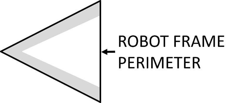
R102
*Starting Configuration – no overhang. In
the Starting Configuration (the physical configuration in which a Robot starts a Match),
no part of the Robot shall extend outside the
vertical projection of the Frame Perimeter,
with the exception of its Bumpers and minor
protrusions such as bolt heads, fastener ends, rivets, cable ties, etc.
If a Robot is designed as intended and each side is pushed
up against a vertical wall (in Starting Configuration
and with Bumpers removed), only the Frame Perimeter (or minor protrusions) will be in
contact with the wall.
The allowance for
minor protrusions in this rule is intended to allow protrusions that are both
minor in extension from the Frame Perimeter and
cross-sectional area.
If a Robot uses interchangeable Mechanisms
per I103, Teams should be prepared to show compliance with this
rule and R105 in all configurations.
R103 *Robot weight limit. The Robot
weight must not exceed 125 lbs. (~56 kg). When determining weight, the basic Robot structure and all elements of all additional Mechanisms that might be used in a single
configuration of the Robot shall be weighed
together (see I103).
For the purposes of determining compliance
with the weight limitations, the following items are excluded:
A.
Robot Bumpers,
B. Robot battery and its associated half of the Anderson
cable quick connect/disconnect pair (including no more than 12 in. (~30 cm) of
cable per leg, the associated cable lugs, connecting bolts, and insulation),
and
C.
tags used for location detection systems if provided by the event.
R104
Starting Configuration – max size. A Robot’s Starting Configuration may not have a Frame Perimeter greater than 120 in. (~304 cm) and
may not be more than 4 ft. 6 in. (~137 cm) tall.
Be sure to
consider the size of the Robot on its cart to
make sure it will fit through doors. Also consider the size of the Robot to ensure that it will fit into a shipping
crate, vehicle, etc.
Note that rules contained
in Section 9.4 BUMPER Rules may impose additional
restrictions on Robot design.
R105
Robot extension limit. Robots
may not extend more than 48 in. (~121 cm) beyond their Frame Perimeter.
Figure 9‑2 Frame
Perimeter extension
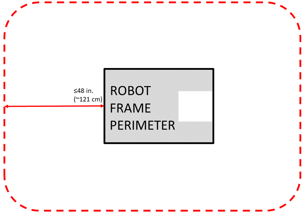
Teams should
expect to have to demonstrate a Robot’s ability
to constrain itself per above during inspection. Constraints may be implemented
with either hardware or software.
See Section 7 Game Rules: ROBOTS for height and
extension restrictions for various areas of the Field.
R201
*No digging into carpet.
Traction devices must not have surface features that could damage the Arena (e.g. metal, sandpaper, hard plastic studs,
cleats, hook-loop fasteners or similar attachments). Traction devices include
all parts of the Robot that are designed to
transmit any propulsive and/or braking forces between the Robot and Field carpet.
R202
*No exposed sharp edges.
Protrusions from the Robot and exposed surfaces
on the Robot shall not pose hazards to the Arena elements (including GAME
PIECES) or people.
R203
*General safety. Robot parts shall not be made from hazardous
materials, be unsafe, cause an unsafe condition, or interfere with the
operation of other Robots.
Examples of items
that will violate this rule include (but are not limited to):
a. shields, curtains, or any other devices or materials
designed or used to obstruct or limit the vision of any DRIVE TEAM members and/or interfere with their
ability to safely control their Robot,
b. speakers, sirens, air horns, or other audio devices that
generate sound at a level sufficient to be a distraction,
c. any devices or decorations specifically intended to jam or
interfere with the remote sensing capabilities of another Robot, including vision systems, acoustic range
finders, sonars, infrared proximity detectors, etc. (e.g. including imagery on
your Robot that, to a reasonably astute
observer, mimics the retro-reflective features of vision targets described in Section 5.9 Vision Targets),
d. exposed lasers other than Class I,
e. flammable gasses,
f. any device intended to produce flames or pyrotechnics,
g. hydraulic fluids or hydraulic items,
h. switches or contacts containing liquid mercury,
i. circuitry used to create voltages in excess of 24 Volts,
j. any ballast not secured sufficiently, including loose
ballast e.g. sand, ball bearings, etc., such that it may become loose during a Match,
k. exposed, untreated hazardous materials (e.g. lead weights)
used on the Robot. These materials may be
permitted if painted, encapsulated, or otherwise sealed to prevent contact.
These materials may not be machined in any way at an event.
l. tire sealant, and
m. high intensity light sources used on the Robot (e.g. super bright LED sources marketed as
‘military grade’ or ‘self-defense’) may only be illuminated for a brief time
while targeting and may need to be shrouded to prevent any exposure to participants.
Complaints about the use of such light sources will be followed by
re-inspection and possible disablement of the device.
R204
*GAME PIECES stay with the Field. Robots must
allow removal of GAME PIECES from the Robot and the Robot
from Field elements while Disabled and powered off.
Robots will not be
re-enabled after the Match, so teams must be
sure that GAME PIECES and Robots can be quickly, simply, and safely removed.
Teams are
encouraged to consider H312 when developing their ROBOTS.
R205
*Don’t contaminate the Field. Lubricants may be used only to reduce
friction within the Robot. Lubricants must not
contaminate the Field or other Robots.
R206
*Don’t damage GAME
PIECES. Robot elements
likely to come in contact with a GAME PIECE shall not pose a significant hazard to the GAME PIECE.
GAME PIECES are
expected to undergo a reasonable amount of wear and tear as they are handled by
ROBOTS, such as scratching or marking. Gouging, tearing off pieces, or
routinely marking GAME PIECES are violations of this rule.
R301
*Individual item cost limit.
No individual, non-KOP item or software shall
have a Fair Market Value (FMV) that exceeds $600 USD.
The total cost of Components purchased in bulk may
exceed $600 USD as long as the cost of an individual Component
does not exceed $600 USD.
Teams should be
ready to show inspectors documentation of FMV
for any Components that appear to be in the
range of the $600 USD limit.
The Analog
Devices IMU MXP Breakout Board, P/N ADIS16448, does not have a published FMV.
This device is considered to comply with this rule regardless of its true FMV.
The FMV of a COTS item is its price defined by a Vendor for the part or an identical functional
replacement. This price must be generally available to all FIRST Robotics Competition teams throughout the build and
competition season (i.e. short-term sale prices or coupons do not reflect FMV),
however teams are only expected to make a good faith effort at determining the
item price and are not expected to monitor prices of Robot
items throughout the season. The FMV is the cost of the item itself and does
not include any duties, taxes, tariffs, shipping, or other costs that may vary
by locality.
The FMV of COTS software is the price, set by the Vendor, to license the software (or piece of the
software) that runs on the Robot for the period
from Kickoff to the end of the FIRST Championship. The FMV of software
licensed free-of-cost, including through the Virtual KOP,
for use on the Robot is $0.
The FMV of
FABRICATED parts is the value of the material and/or labor, except for labor
provided by team members (including sponsor employees who are members of the
team), members of other teams, and/or event provided machine shops. Material
costs are accounted for as the cost of any purchasable quantity that can be
used to make the individual part (i.e. the purchasable raw material is larger
than the FABRICATED part).
Example 1: A team
orders a custom bracket made by a company to the team's specification. The
company’s material cost and normally charged labor rate apply.
Example 2: A team
receives a donated sensor. The company would normally sell this item for $450
USD, which is therefore its FMV.
Example 3: A team
purchases titanium tube stock for $400 USD and has it machined by a local
machine shop. The machine shop is not considered a team sponsor but donates 2
hours of expended labor anyway. The team must include the estimated normal cost
of the labor as if it were paid to the machine shop and add it to the $400 USD.
Example 4: A team
purchases titanium tube stock for $400 USD and has it machined by a local
machine shop that is a recognized sponsor of the team. If the machinists are
considered members of the team, their labor costs do not apply. The total
applicable cost for the part would be $400 USD.
It is in the best
interests of the teams and FIRST to form relationships with as many
organizations as possible. Recognizing supporting companies as sponsors of, and
members in, the team is encouraged, even if the involvement of the sponsor is solely
through the donation of fabrication labor.
Example 5: A team
purchases titanium tube stock for $400 USD and has it machined by another team.
The total applicable cost for the part would be $400 USD.
Example 6: A team
purchases a widget at a garage sale or online auction for $300, but it’s
available for sale from a Vendor for $700. The
FMV is $700.
If a COTS item is part of a modular system that can be
assembled in several possible configurations, then each individual module must
fit within the price constraints defined in this rule.
If the modules
are designed to assemble into a single configuration, and the assembly is
functional in only that configuration, then the total cost of the complete
assembly including all modules must fit within the price constraints defined in
this rule.
In summary, if a Vendor sells a system or a kit, a team must use the
entire system/kit FMV and not the value of its Component
pieces.
Example 7: Vendor A sells a gearbox that can be used with a
number of different gear sets, and can mate with 2 different motors they sell.
A team purchases the gearbox, a gear set, and a motor, then assembles them
together. Each part is treated separately for the purpose of determining FMV since
the purchased pieces can each be used in various configurations.
Example 8: Vendor B sells a robotic arm assembly that a team
wants to use. However, it costs $630 USD, so they cannot use it. The Vendor sells the “hand”, “wrist”, and “arm” as
separate assemblies, for $210 USD each. A team wishes to purchase the 3 items
separately, then reassemble them. This would not be legal, as they are really
buying and using the entire assembly, which has a Fair Market Value of $630
USD.
Example 9: Vendor C sells a set of wheels or wheel modules that
are often used in groups of 4. The wheels or modules can be used in other
quantities or configurations. A team purchases 4 and uses them in the most
common configuration. Each part is treated separately for the purpose of determining
FMV, since the purchased pieces can be used in various configurations.
R302
*Custom parts, generally from
this year only. Fabricated Items created before Kickoff are not
permitted. Exceptions are:
A. Operator Console,
B. Bumpers,
C. battery
assemblies as described in R103-B,
D. Fabricated Items consisting of 1 COTS electrical device (e.g. a motor or motor
controller) and attached Components associated
with any of the following modifications:
a. wires
modified to facilitate connection to a Robot
(including removal of existing connectors),
b. connectors
and any materials to secure and insulate those connectors added (note: passive
PCBs such as those used to adapt motor terminals to connectors are considered
connectors),
c. motor
shafts modified and/or gears, pulleys, or sprockets added, and
d. motors
modified with a filtering capacitor as described in the blue box below R625.
E. COTS items, or functional equivalents, with any of
the following modifications:
a.
non-functional decoration or labeling,
b.
assembly of COTS items per manufacturer
specs, unless the result constitutes a Major Mechanism
as defined in I101, and
c.
work that could be reasonably accomplished in fewer than 30 minutes with
the use of handheld tools (e.g. drilling a small number of holes in a COTS part).
Please note that
this means Fabricated Items from Robots entered in previous FIRST competitions
may not be used on Robots in the CHARGED UP FIRST
Robotics Competition (other than those allowed
per R302-B through -E. Before the
formal start of the build season, teams are encouraged to think as much as they
please about their Robots. They may develop
prototypes, create proof-of-concept models, and conduct design exercises. Teams
may gather all the raw stock materials and COTS
Components they want.
Functionally
equivalent items are items that closely resemble a COTS item in both form and
function. Functional equivalents should be made using similar materials to the
COTS equivalents.
Parts with precision
machined (mill, CNC, etc.) features may still meet part E.c
of this rule if functionally equivalent features could reasonably be made
within the restrictions specified.
Example 1: A team
designs and builds a 2-speed shifting transmission during the fall as a
training exercise. After Kickoff, they utilize all the design principles they
learned in the fall to design their Robot. To
optimize the transmission design for their Robot,
they change the transmission gear ratios and reduce the size, and build 2 new
transmissions, and place them on the Robot. All
parts of this process are permitted activities.
Example 2: A team
re-uses a CHARGED UP-legal motor from a previous Robot
which has had connectors added to the wires. This is permitted, per exception D, because the motor is a COTS
electrical Component.
Example 3: A team
re-uses a piece of aluminum tubing from a previous Robot
which has a precision machined bearing hole in it. On the current Robot, the bearing hole is not used. As the only
function of the hole on the current Robot is
material removal, which does not require precise tolerancing, a functionally
equivalent hole could be made with a hand drill in under 30 minutes and the
part is permitted per part E.c.
R303
*Create new designs and
software, unless they’re public. robot software and designs created before Kickoff are
only permitted if the source files (complete information sufficient to produce
the design) are available publicly prior to Kickoff.
Example 1: A team
realizes that the transmission designed and built in the fall perfectly fits
their need for a transmission to drive the Robot
arm. They build an exact copy of the transmission from the original design plans,
and bolt it to the Robot. This would be
prohibited, as the transmission – although made during the competition season –
was built from detailed designs developed prior to Kickoff.
Example 2: A team
developed an omni-directional drive system for the 2019 competition. In July
2019 they refined and improved the control software, written in C++, to add
more precision and capabilities. They decided to use a similar system for the CHARGED
UP competition. They copied large sections of unmodified code over into the
control software of the new Robot, also written
in C++. This would be a violation of the schedule constraint and is not
allowed.
Example 3: The
same team decides to use LabVIEW as their software environment for CHARGED UP.
Following Kickoff, they use the previously developed C++ code as a reference
for the algorithms and calculations required to implement their
omni-directional control solution. Because they developed new LabVIEW code as
they ported over their algorithms, this is permitted.
Example 4: A
different team develops a similar solution during the fall and plans to use the
developed software on their competition Robot.
After completing the software, they post it in a generally accessible public
forum and make the code available to all teams. Because they have made their
software publicly available before Kickoff, they can use it on their Robot.
Example 5: A team
develops a transmission prior to Kickoff. After completing the project, they
publish the CAD files on a generally accessible public forum and make them
available to all teams. Because they have made the design publicly available
before Kickoff, they can use the design to create an identical transmission,
fabricated after Kickoff, for use on their CHARGED UP Robot.
R304
*During an event, only work
during pit hours. During an event a team
is attending (regardless of whether the team is physically at the event
location), the team may neither work on nor practice with their Robot or Robot
elements outside of the hours that pits are open, with the following
exceptions:
A.
exceptions listed in R302, other than R302-E-c,
B.
software development, and
C.
charging batteries.
For the purposes of
this rule, official events begin as follows:
·
Regionals, District Championships, and FIRST
Championship: at the start of the first designated load-in period, according to
the Public Schedule. If the Public Schedule is not available or there is no
designated load-in period, the events begin at 4pm on the day prior to pits
opening.
·
District Events: when pits open
Examples of
activity prohibited by this rule include:
a. working on the Robot at the
team’s shop after load-in for the event has begun,
b. working on Robot parts at
night at the team’s hotel, and
c. running a 3D printer or other automated manufacturing
process overnight producing ROBOT parts.
Note that E108
and E401 impose additional restrictions on work done on the Robot or Robot
materials while attending an event.
This rule is intended
to increase equity between teams with significant travel to an event and those
nearby (close teams would otherwise have an advantage by being able to work on
their Robot, in their shop, until it’s time to
go to the event).
A Bumper is a
required assembly which attaches to the Robot
frame. Bumpers protect Robots from damaging/being damaged by other Robots and Field
elements. Criteria used in writing these rules include the following:
•
minimize variety of Bumpers so
teams can expect consistency,
•
minimize the amount of design challenge in creating Bumpers,
•
minimize cost of Bumper
materials, and
•
maximize use of relatively ubiquitous materials.
R401
*Bumpers should protect all corners. Robots are required to use Bumpers
to protect all outside corners of the Frame Perimeter.
For adequate protection, at least 6 in. (~16 cm) of Bumper
must be placed on each side of each outside corner (see Figure 9‑3) and
must extend to within ¼ in. (~6 mm) of the Frame
Perimeter corner. If a Frame Perimeter
side is shorter than 12 in. (~31 cm), that entire FRAME PERIMETER side must be
protected by a Bumper (see Figure
9‑4). A round or circular Frame Perimeter,
or segment of the Frame Perimeter, is
considered to have an infinite number of corners, therefore the entire frame or
frame segment must be completely protected by Bumpers.
The dimension
defined in this rule is measured along the Frame
Perimeter. The portion of the Bumper
that extends beyond the corner of the Frame Perimeter
is not included in the 6 in. (~16 cm) requirement. See Figure 9‑3.
Figure 9‑3
Bumper
corner examples
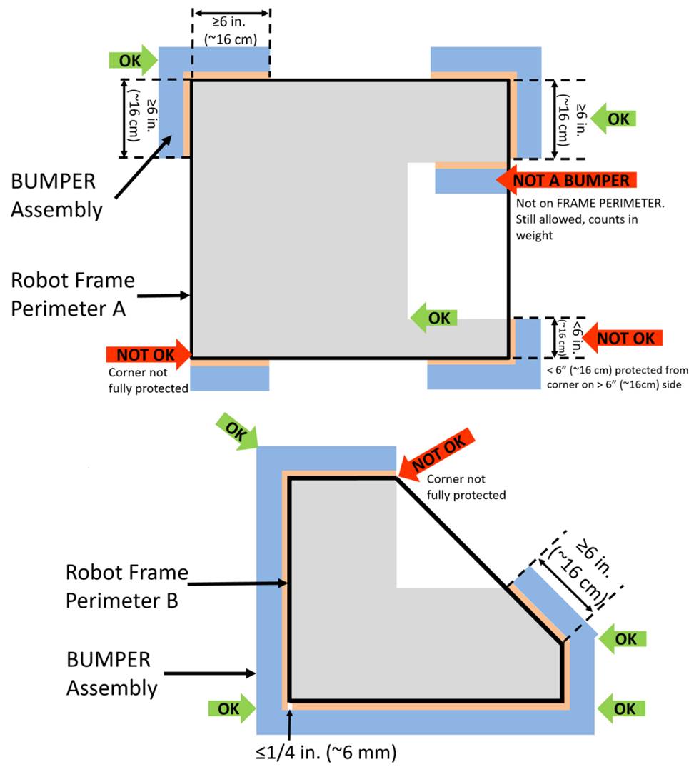
Figure 9‑4
Bumper around full side/corner
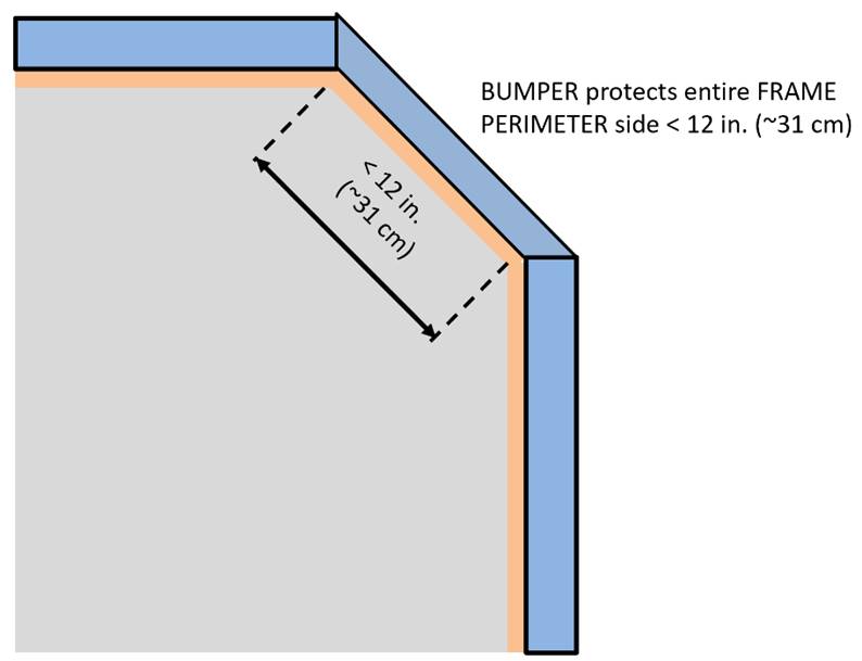
R402
*Bumpers must stay low. Bumpers
must be located entirely within the Bumper Zone,
which is the volume contained between the floor and a
virtual horizontal plane 7½ in. (~19 cm) above the floor in reference to the Robot standing normally on a flat floor. Bumpers do not have to be parallel to the floor.
This measurement
is intended to be made as if the Robot is
resting on a flat floor (without changing the Robot
configuration), not relative to the height of the Robot
from the Field carpet. Examples include:
Example 1: A Robot that is at an angle while navigating the Field has its Bumpers
outside the Bumper Zone. If this Robot were virtually transposed onto a flat floor,
and its Bumpers are in the Bumper Zone, it meets the requirements of this rule.
Example 2: A Robot deploys a Mechanism
which lifts the Bumpers outside the Bumper Zone (when virtually transposed onto a flat
floor). This violates this rule.
R403
*Bumpers shouldn’t move. Bumpers
must not be articulated, relative to the Frame
Perimeter.
R404
*Bumpers must come off. Bumpers
must be designed for quick and easy installation and removal to facilitate
inspection and weighing.
As a guideline, Bumpers should be able to be installed or removed by
2 people in fewer than 5 minutes.
R405
*Bumpers indicate your alliance. Each Robot
must be able to display red or blue Bumpers to
reflect their Alliance color, as assigned in
the Match schedule distributed at the event (as
described in Section 11.1 MATCH Schedules). Bumper markings visible when installed on the Robot, other than the following, are prohibited:
A.
those required per R406,
B.
hook-and-loop tape, snap fasteners, or functional equivalents backed by
the hard parts of the Bumper,
C.
solid white FIRST logos between 4¾ in. (~12 cm) and 5¼ in. wide
(~13 cm) (i.e. comparable to those available in the CHARGED
UP Virtual Kit), and
D.
narrow areas of underlying fabric exposed at seams, corners, or folds.
The Frame Perimeter facing surfaces of Bumpers are not “displayed” and thus this rule does
not apply.
R406
*Team number on bumpers. Team numbers must be displayed and positioned
on the Bumpers such that an observer walking
around the perimeter of the Robot can
unambiguously tell the team’s number from any point of view and meet the
following additional criteria:
A.
consist of only white Arabic numerals at least 4 in. (~11 cm) high, at
least ½ in. (~13 mm) in stroke width,
The ½ in. (~13
mm) stroke width requirement applies to the majority of the stroke. Font
elements less than ½ in. (~13 mm) such as serifs, rounded edges, small
hairlines or gaps, etc. are permitted as long as the majority of the stroke
meets the sizing requirement and the numbers are unambiguous.
B.
must not wrap around sharp corners (less than 160°) of the Frame Perimeter, and
C.
may not substitute logos or icons for numerals.
There is no
prohibition against splitting team numbers onto different sections of Bumper. The intent is that the team’s number is
clearly visible and unambiguous so that Judges, Referees,
Announcers, and other teams can easily identify competing Robots.
This marking is
intended to display the team number only, not to intentionally change the
surface characteristics of the Bumper.
Excessive material usage as part of any team number marking will invite close
scrutiny.
R407
*Bumper weight limit. Each set of Bumpers (including any fasteners and/or structures
that attach them to the Robot) must weigh no
more than 15 lbs. (~6 kg).
If a multi-part
attachment system is utilized (e.g. interlocking brackets on the Robot and the Bumper),
then the elements permanently attached to the Robot
will be considered part of the Robot, and the
elements attached to the Bumpers will be
considered part of the Bumper. Each element
must satisfy all applicable rules for the relevant system.
R408
*Bumper construction. Bumpers
must be constructed as follows (see Figure 9‑7):
A. be backed
by ¾ in. thick (nominal, ~19mm) by 5 in. ± ½ in. (~127 mm ± 12.7 mm) tall
plywood, Oriented Strand Board (OSB) or solid wood (with the exception of
balsa). Small clearance pockets to accommodate minor protrusions permitted per R101 and/or holes needed to access or recess mounting hardware
in the wood backing are permitted, as long as they do not significantly affect
the structural integrity of the Bumper.
¾ in. plywood and
OSB refer to items sold by Vendors as that
material and thickness, teams may not fabricate their own plywood or OSB. Other
engineered woods such as Fiberboard or Particle Board are not likely to survive
the rigors of FIRST Robotics Competition
gameplay and thus not permitted per A.
Note: ¾ in.
plywood is often marked according to the actual dimension (²³⁄₃₂”) not the nominal size. Plywood sold as ²³⁄₃₂” meets the requirements of A.
B. hard Bumper parts allowed per A, E, F, and G must
not extend more than 1 in. (~25 mm) beyond the Frame
Perimeter (measured as shown in Figure 9‑5).
Figure
9‑5 Hard parts of Bumper corners
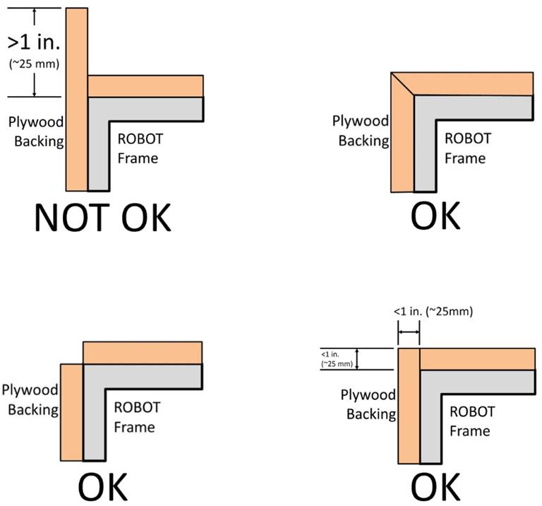
C. use a
stacked pair of 2½ in. (~63 mm) round, petal, or hex “pool noodles” (solid or
hollow) as the Bumper cushion material (see Figure 9‑7). All pool noodles used in a Bumper
set (e.g. red set of Bumpers) may not be
modified (with the exception of cutting to length or cutting to facilitate
mating pool noodles at the corners as required by R409) or
deformed and must be the same diameter, cross section, and density (e.g. all
round hollow or all hex solid). Per R409 cushion material
may extend beyond the end of the plywood in order to fill a corner (see Figure 9‑8). To assist in applying the fabric covering, soft fasteners may be
used to attach the pool noodles to the wood backing, so long as the cross
section in Figure 9‑7 is not significantly altered (e.g. tape compressing
the pool noodles).
“2½ in. (~63 mm)
pool noodles” are pool noodles either sold as 2½ in. (~63 mm) diameter or that
measure between 2¼ in. (~57 mm) pool noodles and 2¾ in. (~70 mm) diameter.
All pool noodles
used on a Robot must be the same in order to
maintain the desired interaction between Robots
in the cases of Bumper-to-Bumper contact. Bumpers
containing pool noodles of vastly different construction may cause a “ramp”
effect when interacting with other Bumpers.
Minor noodle
compression as a result of smoothing Bumper
fabric or rounding a Frame Perimeter corner is
not considered deformed. Any compression beyond that, e.g. for the purposes of
flattening the pool noodle, is deformation and a violation of C.
D.
be covered with a rugged, smooth cloth with no additional coating
applied by the team except for BUMPER markings permitted per R405
(multiple layers of cloth and seams are permitted if needed to accommodate R405 and/or R406, provided the cross
section in Figure 9‑7 is not significantly altered).
Silk and bedding
are not considered rugged cloths, however 1000D Cordura is. Tape (e.g. gaffer’s
tape) matching the Bumper color is allowed to
patch small holes on a temporary basis.
It is expected
that there may be multiple layers of cloth as fabric is folded to accommodate
the corners and seams of Bumpers.
The cloth must completely enclose all exterior
surfaces of the wood and pool noodle material when the Bumper is installed on the Robot.
The fabric covering the Bumpers must be solid
in color.
E. optionally
use metal angle, as shown in Figure 9‑7 or other fasteners (e.g. staples,
screws, adhesives, etc.) to clamp cloth.
F. optionally
use metal brackets (i.e. angle or sheet metal) or other fasteners (e.g.
staples, screws, adhesives, etc.) to attach Bumper
segments to each other (see Figure 9‑6).
Figure
9‑6 Example uses of brackets in Bumper
corners
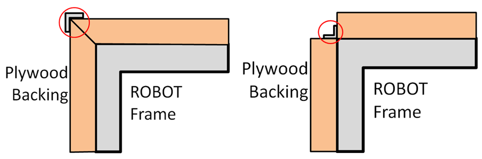
G. must
attach to the Frame Perimeter of the Robot with a rigid fastening system to form a tight,
robust connection to the main structure/frame (e.g. not attached with
hook-and-loop tape, tape, or cable ties). The attachment system must be
designed to withstand vigorous game play. All removable fasteners (e.g. bolts, locking
pins, pip-pins, etc.) will be considered part of the Bumpers.
Figure 9‑7 Bumper
vertical cross section
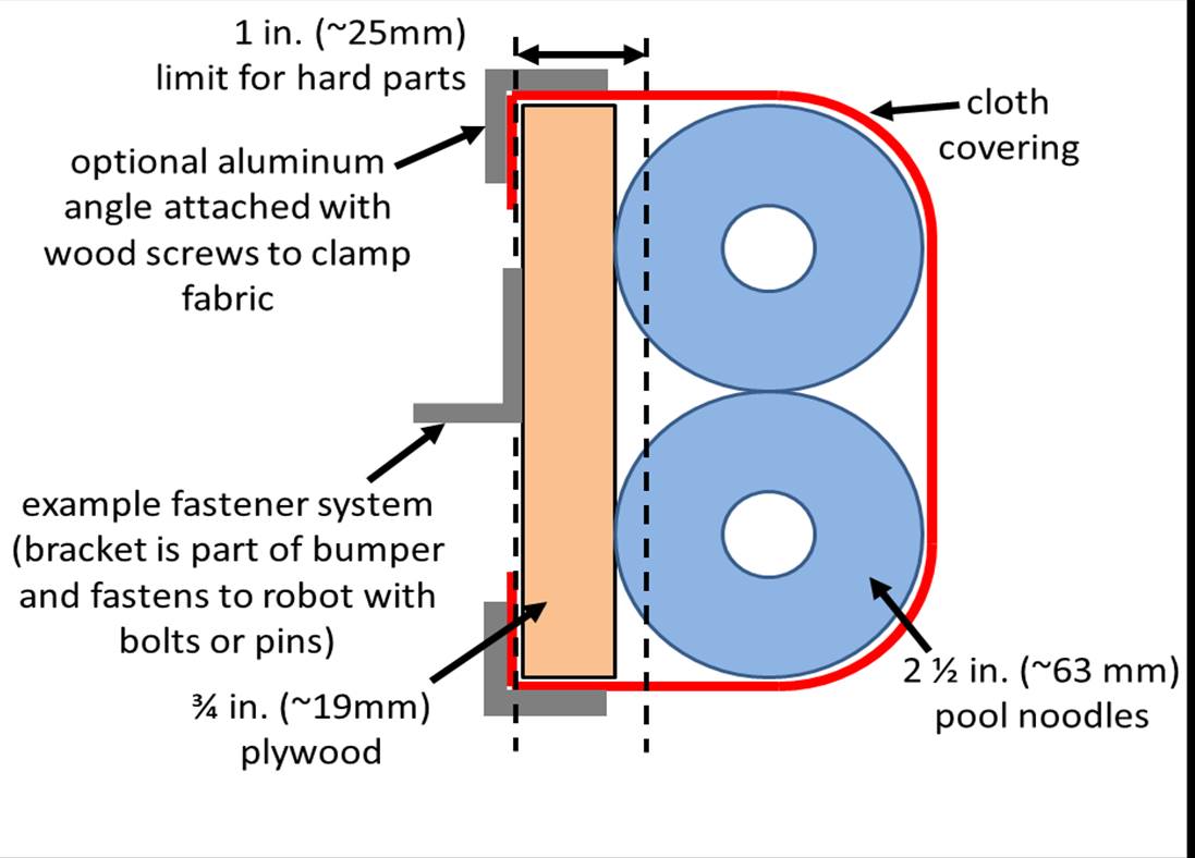
R409
*Fill Bumper corners. Corner joints between Bumpers must be filled with pool noodle material.
Examples of implementation are shown in Figure 9‑8.
Figure
9‑8 Soft parts of Bumper corners
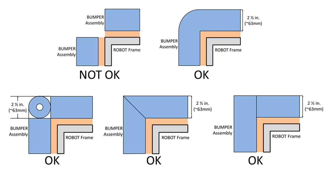
R410
*Bumpers must be supported. Bumpers
must be supported by the structure/frame of the Robot
(see Figure 9‑9). To be considered supported, a minimum of ½ in. (~13 mm)
at each end of each Bumper wood segment must be
backed by the Frame Perimeter (≤¼ in.
gap, ~6mm). “Ends” exclude hard Bumper parts
which extend past the Frame Perimeter permitted
by R408-B. Additionally, any gap between the backing
material and the frame:
A.
must not be greater than ¼ in. (~6 mm) deep or
B.
not more than 8 in. (~20 cm) wide
Figure
9‑9 Bumper support examples
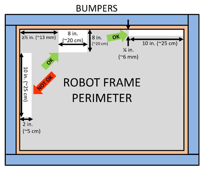
The intent of
this rule is to make sure the Bumper wood is
properly supported to minimize the likelihood of breakage on impact. Flexible Robot elements, such as thin plastic, do not
accomplish this intent and are not considered “structure/frame” of the Robot.
9.5
Motors & Actuators
R501
*Allowable motors. The only motors and actuators permitted include the
following (in any quantity):
Table 9‑1 Motor allowances
|
Motor Name
|
Part Numbers Available
|
|
AndyMark
9015
|
am-0912
|
AndyMark 9015
|
|
AndyMark
NeveRest
|
am-3104
|
|
|
AndyMark
PG
|
am-2161 (alt. PN am-2765)
|
am-2194 (alt. PN am-2766)
|
|
AndyMark
RedLine Motor
|
am-3775
|
am-3775a
|
|
AndyMark
Snow Blower Motor
|
am-2235
|
am-2235a
|
|
Banebots
|
am-3830
M7-RS775-18
RS775WC-8514
|
M5
– RS550-12
RS550VC-7527
RS550
|
|
CIM
|
FR801-001
M4-R0062-12
AM802-001A
217-2000
PM25R-44F-1005
|
PM25R-45F-1004
PM25R-45F-1003
PMR25R-45F-1003
PMR25R-44F-1005
am-0255
|
|
CTR Electronics/VEX Robotics Falcon 500
|
217-6515
am-6515
|
19-708850
am-6515_Short
|
|
Current/former
KOP automotive motors
|
Denso AE235100-0160
Denso 5-163800-RC1
Denso 262100-3030
|
Denso 262100-3040
Bosch 6 004 RA3 194-06
Johnson Electric JE-PLG-149
Johnson Electric JE-PLG-410
|
|
Nidec Dynamo
BLDC Motor
|
am-3740
|
DM3012-1063
|
|
Playing with Fusion Venom
|
BDC-10001
|
|
|
REV Robotics
HD Hex
|
REV-41-1291
|
|
|
REV Robotics NEO Brushless
|
REV-21-1650 (v1.0 or v1.1)
|
am-4258
am-4258a
|
|
REV Robotics
NEO 550
|
REV-21-1651
|
am-4259
|
|
VEX BAG
|
217-3351
|
|
|
VEX Mini-CIM
|
217-3371
|
|
|
West
Coast Products RS775 Pro
|
217-4347
|
|
|
Electrical solenoid actuators, no
greater than 1 in. (nominal) stroke and rated electrical input power no
greater than 10 watts (W) continuous duty at 12 volts (VDC) (if qualifying
actuator is then used at 24V, it must be approved by the manufacturer for use
at 24V)
|
|
Fans, no
greater than 120mm (nominal) size and rated electrical input power no greater
than 10 watts (W) continuous duty at 12 volts (VDC)
|
|
Hard drive motors part of a legal COTS
computing device
|
|
Factory
installed vibration and autofocus motors resident in COTS computing devices (e.g. rumble motor in a
smartphone).
|
|
PWM COTS
servos with a retail cost < $75.
|
|
Motors integral to a COTS sensor (e.g. LIDAR, scanning
sonar, etc.), provided the device is not modified except to facilitate
mounting
|
|
1 compressor
compliant with R806 and
used to compress air for the Robot’s pneumatic system
|
|
Linear actuators rated for 12V and wired downstream of a
breaker 20A or less
|
For servos, note
that the roboRIO is limited to a max current output of 2.2A on the 6V rail
(12.4W of electrical input power). Teams should make sure that their total
servo power usage remains below this limit at all times.
Given the
extensive amount of motors allowed on the Robot,
teams are encouraged to consider the total power available from the Robot battery during the design and build of the Robot. Drawing large amounts of current from many
motors at the same time could lead to drops in Robot
battery voltage that may result in tripping the main breaker or trigger the
brownout protection of the roboRIO. For more information about the roboRIO
brownout protection and measuring current draw using the PDP/PDH, see roboRIO
Brownout and Understanding Current Draw.
AndyMark PG
Gearmotors are sold with labeling based on the entire assembly. Assemblies
labeled am-3651 through am-3656 contain legal motors specified in the table
above. These motors may be used with or without the provided gearbox.
R502
*Don’t modify motors (mostly).
The integral mechanical and electrical system of any motor must not be
modified. Motors, servos, and electric solenoids used on the Robot shall not be modified in any way, except as
follows:
A.
The mounting brackets and/or output shaft/interface may be modified to
facilitate the physical connection of the motor to the Robot and actuated part.
B.
The electrical leads may be trimmed to length as necessary and
connectors or splices to additional wiring may be added.
C.
The locking pins on the window motors (P/N 262100-3030 and 262100-3040) may
be removed.
D.
The connector housings on KOP automotive
motors listed in Table 9‑1 may be modified to facilitate lead
connections.
E.
Servos may be modified as specified by the manufacturer (e.g.
re-programming or modification for continuous rotation).
F.
The wiring harness of the Nidec Dynamo BLDC Motor may be modified as
documented by FIRST in Nidec
Dynamo BLDC Motor with Controller.
G.
Minimal labeling may be applied to indicate device purpose, connectivity,
functional performance, etc.
H.
Any number of #10-32 plug screws may be removed from the Falcon 500.
I.
Insulation may be applied to electrical terminals.
J.
Repairs, provided the performance and specifications are unchanged.
K.
Maintenance recommended by the manufacturer.
The intent of
this rule is to allow teams to modify mounting tabs and the like, not to gain a
weight reduction by potentially compromising the structural integrity of any
motor.
R503 *Power (most) actuators off of approved devices. With the exception of servos,
fans, or motors integral to sensors of COTS
computing devices permitted in R501, each actuator must
be controlled by a power regulating device. The only power regulating devices
for actuators permitted on the Robot include:
A. motor
controllers,
a. DMC
60/DMC 60c Motor Controller (P/N 410-334-1, 410-334-2),
b. Jaguar
Motor Controller (P/N MDL-BDC, MDL-BDC24, and 217-3367) connected to PWM only,
c. Nidec
Dynamo, BLDC Motor with Controller to control integral actuator only (P/N
840205-000, am-3740)
d. SD540
Motor Controller (P/N SD540x1, SD540x2, SD540x4, SD540Bx1, SD540Bx2, SD540Bx4,
SD540C),
e. Spark
Motor Controller (P/N REV-11-1200, am-4260),
f. Spark
MAX Motor Controller (P/N REV-11-2158, am-4261),
g. Talon
FX Motor Controller (P/N 217-6515, 19-708850, am-6515, am-6515_Short) for
controlling integral Falcon 500 only,
h. Talon
Motor Controller (P/N CTRE_Talon, CTRE_Talon_SR, and am-2195),
i. Talon
SRX Motor Controller (P/N 217-8080, am-2854, 14-838288),
j. Venom
Motor with Controller (P/N BDC-10001) for controlling integral motor only,
k. Victor
884 Motor Controller (P/N VICTOR-884-12/12),
l. Victor
888 Motor Controller (P/N 217-2769),
m. Victor SP Motor
Controller (P/N 217-9090, am-2855, 14-868380), and
n. Victor
SPX Motor Controller (P/N 217-9191, 17-868388, am-3748),
B. relay modules,
a. Spike
H-Bridge Relay (P/N 217-0220 and SPIKE-RELAY-H),
b. Automation
Direct Relay (P/N AD-SSR6M12-DC-200D, AD-SSRM6M25-DC-200D, AD-SSR6M40-DC-200D),
and
c. Power
Distribution Hub (PDH) switched channel (P/N REV-11-1850)
for controlling non-actuator CUSTOM CIRCUITS
only,
C. pneumatics
controllers,
a. Pneumatics
Control Module (P/N am-2858, 217-4243) and
b. Pneumatic
Hub (P/N REV-11-1852).
Note: The Automation
Direct Relays are single directional. Per R504 they may not be wired together in an attempt to provide
bi-directional control.
R504
*Don’t overload controllers.
Each power regulating device may control electrical
loads per Table 9‑2. Unless otherwise noted, each power regulating
device shall control 1 and only 1 electrical load.
Table 9‑2
Power regulating device allotments
|
Electrical Load
|
Motor Controller
|
Relay Module
|
Pneumatics Controller
|
|
AndyMark RedLine Motor
Banebots
CIM
REV Robotics NEO Brushless
REV Robotics NEO 550
VEX Mini-CIM
WCP RS775 Pro
|
Yes
|
No
|
No
|
|
AndyMark 9015
VEXpro BAG
|
Yes
(up to 2 per controller)
|
No
|
No
|
|
AndyMark PG
KOP Automotive
Motors
NeveRest
Snow Blower
Motor
REV Robotics
HD Hex
|
Yes
(up to 2 per controller)
|
Yes
|
No
|
|
Linear Actuator
|
Yes
(20A breaker max)
|
Yes
(20A breaker max)
|
No
|
|
CTR
Electronics/VEX Falcon 500
Nidec Dynamo
BLDC Motor w/ Controller
Playing With
Fusion Venom
|
Yes
(integrated controller only)
|
No
|
No
|
|
Compressor
|
No
|
Yes
|
Yes
|
|
Pneumatic
Solenoid Valves
|
No
|
Yes
(multiple)
|
Yes
(1 per channel)
|
|
Electric Solenoids
|
Yes
(multiple)
|
Yes
(multiple)
|
Yes
(1 per channel)
|
|
Custom Circuits
|
Yes
(multiple)
|
Yes
(multiple)
|
Yes
(multiple)
|
R505
*Control servos safely.
Servos must be connected to, and only to, 1 of the following:
A.
PWM ports on the roboRIO,
B.
PWM ports on a WCP Spartan Sensor Board (P/N WCP-0045), or
C.
REV Robotics Servo Power Module (P/N
REV-11-1144).
In order to maintain safety, the rules in this section apply
at all times while at the event, not just while the Robot
is on the Field for Matches.
R601
*Battery limit – everyone has
the same power. The only legal source of electrical energy for the Robot during the competition, the Robot battery, must be 1 and only 1 non-spillable
sealed lead acid (SLA) battery with the following specifications:
A.
Nominal voltage: 12V
B.
Nominal capacity at 20-hour discharge rate: minimum 17Ah, maximum 18.2Ah
C.
Shape: Rectangular
D.
Nominal Dimensions: 7.1 in. x 3 in. x 6.6 in., +/- .1 in. for each
dimension (~ 180 mm x 76mm x 168 mm, +/- 2.5 mm for each dimension)
E.
Nominal weight: 11lbs. to 14.5 lbs. (~5 kg. to 6.5 kg.)
F.
Terminals: Nut and bolt style
Examples of
batteries which meet these criteria include:
a. Enersys (P/N NP18-12, NP18-12B, NP18-12BFR),
b. MK Battery (P/N ES17-12),
c. Battery Mart (P/N SLA-12V18),
d. Sigma (P/N SP12-18),
e. Universal Battery (P/N UB12180),
f. Power Patrol (P/N SLA1116),
g. Werker Battery (P/N WKA12-18NB),
h. Power Sonic (P/N PS-12180NB),
i. Yuasa (P/N NP18-12B),
j. Panasonic (P/N LC-RD-1217),
k. Interstate Batteries (P/N BSL1116), and
l. Duracell Ultra Battery (P/N DURA12-18NB).
Teams should be
aware that they may be asked to provide documentation of the specifications of
any battery not listed above.
Batteries should
be charged in accordance with manufacturer’s specification. (Please see the FIRST
Safety Manual for additional information.)
R602
*Other batteries for cameras
or computers only. COTS USB battery
packs with a capacity of 100Wh or less (20000mAh at 5V) and 5V, 2.5 Amp max
output per port, or batteries integral to and part of a COTS computing device or self-contained camera (e.g.
laptop batteries, GoPro style camera, etc.) may be used to power COTS computing devices and any peripheral COTS input or output devices connected to the COTS computing device provided they are:
A.
securely fastened to the Robot,
B.
connected only using unmodified COTS
cables, and
C.
charged according to manufacturer recommendations.
A cots computing device is a non-roboRIO device used to
process or collect sensor information (e.g. a “smart flashlight” is not a cots computing device).
R603
*Charge batteries with safe
connectors. Any battery charger used to charge a Robot battery must have the corresponding Anderson SB
connector installed.
R604
*Charge batteries at a safe
rate. Any battery charger used to charge a Robot
battery may not be used such that it exceeds 6-Amp peak charge current.
R605
*Batteries are not ballast. No batteries other than those allowed per R601
and R602 are allowed on the Robot,
whether or not they are being used to supply power.
For example,
teams may not use additional batteries as extra weight on their Robots.
R606
*Secure the battery. The
Robot battery must be secured such that it will
not dislodge during vigorous Robot interaction
including if the Robot is turned over or placed
in any arbitrary orientation.
R607
*Insulate battery connections.
Each electrical terminal on the Robot battery,
main breaker, and their connections (lugs, stripped wire ends, etc.) to the
wire must be fully insulated at all times.
R608
*Limit non-battery energy. Non-electrical sources of energy used by the Robot (i.e., stored at the start of a Match) shall come only from the following sources:
A.
compressed air stored in the pneumatic system that has been charged in
compliance with R806 and R807,
B.
a change in the altitude of the Robot
center of gravity,
C.
storage achieved by deformation of Robot
parts,
D.
closed-loop COTS pneumatic (gas) shocks,
or
E.
air-filled (pneumatic) wheels.
R609
*Connect main power safely.
The 1 Robot battery, a single pair of Anderson
Power Products (or APP) 2-pole SB type connectors, the 1 main 120-amp (120A)
surface mount circuit breaker (Cooper Bussman P/N CB185-120, CB185F-120, CB285-120
CB285F-120, CB285120F or Optifuse P/N 153120, 253120), and the 1 power distribution
device (CTR Electronics Power Distribution Panel, PDP,
P/N am-2856, 217-4244, 14-806880 or REV Robotics
Power Distribution Hub, PDH, P/N REV-11-1850) shall
be connected with 6 AWG (7 SWG or 16 mm2) copper wire or larger, with no
additional devices or modifications (with the exception of monitoring circuitry
permitted by R625), as shown in Figure 9‑10.
Figure
9‑10 Electrical connection diagram
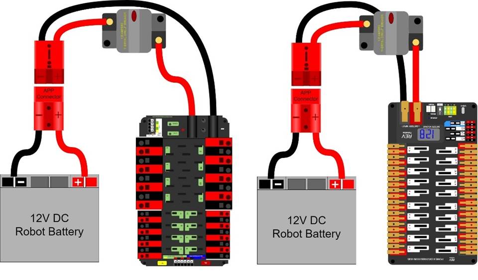
“SB type” refers
to SB type only (e.g. SB-50, SB-120, etc.), not SBS or any other part type
beginning with SB. All batteries supplied by FIRST (such as Spare Parts
and international batteries) will have a red or pink SB50 connector installed which
may not be removed.
The pink connectors
included in the CHARGED UP KOP mate with the red
SB50 connector.
R610
*1 breaker per circuit.
All circuits, with the exceptions of those listed in R615 and
R617, must connect to, and have power sourced solely by, a
single protected 12VDC WAGO connector pair (i.e. the load terminals, as shown
in Figure 9‑10) of the PDP/PDH, not the M6 cap screws.
R611
*The Robot frame is not a wire. All wiring and electrical
devices shall be electrically isolated from the Robot
frame. The Robot frame must not be used to
carry electrical current.
Compliance with
this rule is checked by observing a >120Ω resistance between either
the (+) or (-) post within the APP connector that is attached to the PDP/PDH and any point on the Robot.
All legal motor
controllers with metal cases are electrically isolated. They may be mounted
directly to Robot frame Components.
Note that some
cameras, decorative lights, and sensors (e.g. some encoders, some IR sensors,
etc.) have grounded enclosures or are manufactured with conductive plastics.
These devices must be electrically isolated from the Robot
frame to ensure compliance with this rule.
R612
*Must be able to turn robot on and off safely. The 120A circuit breaker
must be quickly and safely accessible from the exterior of the Robot. This is the only 120A circuit breaker allowed
on the Robot.
Examples
considered not “quickly and safely accessible” include breakers covered by an
access panel or door, or mounted on, underneath or immediately adjacent to
moving Components.
It is strongly
recommended that the 120A circuit breaker location be clearly and obviously
labeled so it can be easily found by Field Staff
during a Match.
R613
*Electrical system must be
inspectable. The PDP/PDH, associated
wiring, and all circuit breakers must be visible for inspection.
“Visible for
inspection” does not require that the items be visible when the ROBOT is in STARTING
CONFIGURATION, provided the team can make the items viewable during the
inspection process.
R614
*No high voltage allowed.
Any active electrical item that is not an actuator
(specified in R501) or core control system item (specified in R710) is considered a Custom Circuit.
Custom Circuits shall not produce voltages
exceeding 24V.
R615 *Power roboRIO as specified. The roboRIO power
input must be connected to either:
A.
the dedicated supply terminals on the PDP
shown in Figure 9‑11 or
Figure 9‑11
roboRIO power source on a PDP
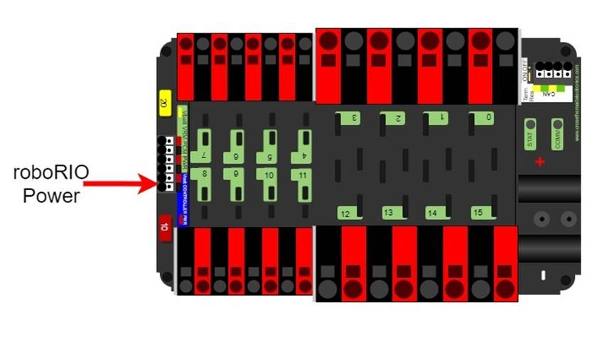
B.
the terminals of 1 of the non-switchable fused channels on the PDH (20,21,22) with a 10A fuse installed in the
associated fuse holder.
No other electrical load shall be
connected to that channel.
Figure 9‑12 roboRIO power source on a PDH
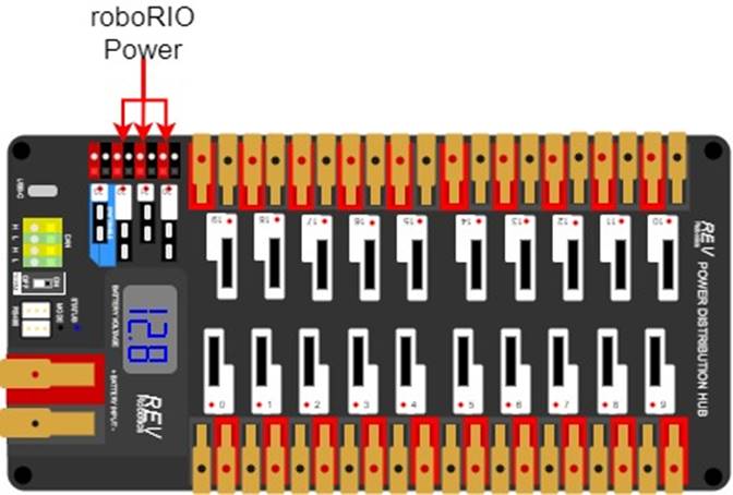
R616
*Power radio as specified –
Part 1. The wireless bridge (radio) power must be supplied by either:
A.
the 12V 2A output of a CTR Electronics Voltage Regulator Module (VRM) (P/N am-2857, 217-4245), as shown in Figure 9‑13, and must be the only load connected to those terminals or
Figure 9‑13
Radio power source from a VRM
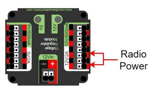
B.
using an Ethernet cable between a REV Radio Power Module (RPM) (P/N REV-11-1856)
and the “18-24v POE” Ethernet port on the wireless bridge.
Note that this
prohibits using any other active POE injector device to power the radio but
does not prohibit using any Passive Conductors
to inject the VRM power into an Ethernet cable
plugged into the radio port labeled “18-24v POE.”
R617
*Power radio as specified –
Part 2. The device supplying power to the wireless bridge per R616 must be connected to either:
A.
the designated supply terminals at the end of the PDP, as shown in Figure 9‑14. With the
exception of a single CTR Electronics Pneumatics Control Module (PCM, P/N am-2858) or REV Robotics Pneumatic Hub (PH,
P/N REV-11-1852), no other electrical load shall be connected to these PDP terminals.
Figure 9‑14
VRM, PCM, and RPM power source on a PDP
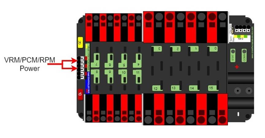
B.
the terminals of 1 of the non-switchable fused channels on the PDH (20,21,22) with a 10A fuse installed in the
associated fuse holder. No other electrical load shall be connected to that
channel.
Figure 9‑15 VRM and RPM power source on a PDH
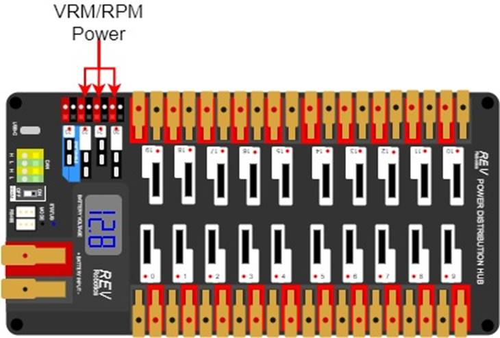
R618
*Use PDP/PDH terminals as
designed. Only 1 wire shall be connected to
each terminal on the PDP/PDH.
If multi-point
distribution of circuit power is needed (e.g. to provide power to multiple PCMs and/or VRMs from
1 20A circuit), then all incoming wires may be appropriately spliced into the
main lead (e.g. using an insulated terminal
block, crimped splice or soldered wire splice), and the single main lead
inserted into the terminal to power the circuit.
R619
*Only use specified circuit
breakers in PDP/PDH. The only circuit
breakers permitted for use in the PDP/PDH are:
A.
Snap Action VB3-A Series or AT2-A, terminal style F57, 40A rating or
lower,
B.
Snap Action MX5-A or MX5-L Series, 40A rating or lower, and
C.
REV Robotics ATO auto-resetting breakers 40A
rating or lower.
R620
*Only use specified fuses in PDP/PDH. The only fuses permitted for use in the PDP/PDH are mini automotive
blade fuses (ATM style) with the following values:
A.
for the PDP, values matching the value
printed on the device’s corresponding fuse holder and
B.
for the PDH, 15A or lower with the
exception of a single 20A fuse for powering a PCM or PH.
Note that these
fuses must be pressed very firmly to seat properly. Improper seating can cause a
device to reboot upon impact.
R621
*Protect circuits with
appropriate circuit breakers. Each branch circuit must be protected by 1 and only 1
circuit breaker or fuse on the PDP/PDH per Table 9‑3. No other electrical load can be connected to the breaker or fuse supplying
this circuit.
Table 9‑3
Branch circuit protection requirements
|
Branch Circuit
|
Circuit Breaker Value
|
Quantity Allowed Per Breaker
|
|
Motor Controller
|
Up to 40A
|
1
|
|
Custom
Circuit
|
Up
to 40A
|
No
limit
|
|
Automation Direct
Relay 40A (*6M40*)
|
Up to 40A
|
1
|
|
Fans permitted per R501 and not already part of COTS computing devices
|
Up
to 20A
|
No
limit
|
|
Spike Relay
Module
|
Up to 20A
|
1
|
|
Automation Direct Relay 25A (*6M25*)
|
Up
to 20A
|
1
|
|
PCM/PH –
with compressor
|
Up to 20A
|
1
|
|
Additional VRM
(non-radio)/Additional PCM/PH
(non-compressor)
|
Up
to 20A
|
3
total
|
|
Automation Direct
Relay 12A (*6M12*)
|
Up to 10A
|
1
|
This rule does
not prohibit the use of smaller value breakers in the PDP/PDH
or any fuses or breakers within Custom Circuits
for additional protection.
R622
*Use appropriately sized wire.
All circuits shall be wired with appropriately sized insulated copper wire (Signal Level cables don’t have to be copper):
Table 9‑4 Breaker and wire sizing
Wires that are recommended by the device
manufacturer or originally attached to legal devices are considered part of the
device and by default legal. Such wires are exempt from this rule.
In order to show
compliance with these rules, teams should use wire with clearly labeled sizes
if possible. If unlabeled wiring is used, teams should be prepared to
demonstrate that the wire used meets the requirements of this rule (e.g. wire
samples and evidence that they are the required size).
R623
*Use only appropriate
connectors. Branch circuits may include intermediate elements such as COTS connectors, splices, COTS
flexible/rolling/sliding contacts, and COTS
slip rings, as long as the entire electrical pathway is via appropriately
gauged/rated elements.
Slip rings
containing mercury are prohibited per R203.
R624
*Use specified wire colors
(mostly). All non-Signal Level wiring
with a constant polarity (i.e., except for outputs of relay modules, motor
controllers, or sensors) shall be color-coded along their entire length from
the manufacturer as follows:
A.
red, yellow, white, brown, or black-with-stripe on the positive (e.g.
+24VDC, +12VDC, +5VDC, etc.) connections
B.
black or blue for the common or negative side (-) of the connections
Exceptions to this rule include:
C.
wires that are originally attached to legal devices and any extensions
to these wires using the same color as the manufacturer
D.
Ethernet cable used in POE cables
R625
*Don’t modify critical power
paths. Custom Circuits shall not
directly alter the power pathways between the Robot
battery, PDP/PDH, motor controllers, relays
(per R503-B), motors and actuators (per R501),
pneumatic solenoid valves, or other elements of the Robot
control system (items explicitly mentioned in R701). Custom
high impedance voltage monitoring or low impedance current monitoring circuitry
connected to the Robot’s electrical system is
acceptable, if the effect on the Robot outputs
is inconsequential.
A noise filter may
be wired across motor leads or PWM leads. Such filters will not be considered Custom Circuits and violate neither this rule nor R717.
Acceptable signal
filters must be fully insulated and must be 1 of the following:
·
a 1 microfarad (1 µF) or less,
non-polarized, capacitor may be applied across the power leads of any motor on
your Robot (as close to the actual motor leads
as reasonably possible) or
·
a resistor may be used as a shunt load
for the PWM control signal feeding a servo.
R701
*Control the robot with a roboRIO. Robots
must be controlled via 1 programmable NI roboRIO or roboRIO 2.0 (P/N am3000 or am3000a,
both versions referred to throughout this manual as “roboRIO”), with image version
2023_v3.1 or later.
There are no
rules that prohibit co-processors, provided commands originate from the roboRIO
to enable and disable all power regulating devices. This includes motor
controllers legally wired to the CAN bus.
R702
*Communicate with the Robot with the specified radio. 1 OpenMesh wireless
bridge (P/N: OM5P-AN or OM5P-AC), that has been configured with the appropriate
encryption key for your team number at each event, is the only permitted device
for communicating to and from the Robot during
the Match.
R703
*Use specific Ethernet port
for roboRIO. The roboRIO Ethernet port must be connected to the wireless
bridge port labeled “18-24 vPOE” (either directly, via a network switch, via an
RPM, or via a CAT5 Ethernet pigtail).
Note: Placing a
switch between the roboRIO and radio may impede the ability for Field Staff to troubleshoot roboRIO connection issues
on the Field. Teams may be asked to connect directly
between the radio and the roboRIO as part of troubleshooting efforts.
R704
*Only use allowed ports and
bandwidth to communicate with the robot. Communication between the Robot and the Operator
Console may not exceed 4 Mbits/second and is restricted to network ports
listed in Table 9‑5.
Table 9‑5
Open FMS ports
|
Port
|
Designation
|
Bi-directional?
|
|
UDP/TCP 1180-1190
|
Camera data from the roboRIO to
dashboard software when the camera is connected the roboRIO via USB
|
Yes
|
|
TCP 1735
|
SmartDashboard
|
Yes
|
|
UDP 1130
|
Dashboard-to-Robot control data
|
Yes
|
|
UDP 1140
|
Robot-to-Dashboard status
data
|
Yes
|
|
HTTP 80
|
Camera connected via switch on
the Robot
|
Yes
|
|
HTTP 443
|
Camera connected via switch on the Robot
|
Yes
|
|
UDP/TCP 554
|
Real-Time Streaming Protocol
for h.264 camera streaming
|
Yes
|
|
UDP/TCP
1250
|
CTRE Diagnostics Server
|
Yes
|
|
UDP/TCP 5800-5810
|
Team use
|
Yes
|
Teams may use these ports as they wish if
they do not employ them as outlined above (i.e. TCP 1180 can be used to pass
data back and forth between the Robot and the Driver
Station Software if the team chooses not to use the camera on USB).
Note that the 4 Mbit
limit will be strictly enforced by the wireless bridge.
The FMS Whitepaper has more details on how to
check and optimize bandwidth usage.
While FIRST
makes every effort to provide a wireless environment that allows teams access
to a full 4 Mbits/second data rate (with about 100 Kbit used for Robot control and status), at some events wireless
conditions may not accommodate this.
R705
*Configure devices for your
team number. The roboRIO, Driver Station
Software, and wireless bridge must be configured to correspond to the correct
team number, per the procedures defined in the FIRST Robotics
Competition Control System documentation.
R706
*Don’t bypass the arena network. All
signals must originate from the Operator Console
and be transmitted to the Robot via the Arena Ethernet network.
R707
*No other wireless allowed. No form of wireless communication shall be used to
communicate to, from, or within the Robot,
except those required per R702, R706, and
tags used for location detection systems if provided by the event.
Devices that
employ signals in the visual spectrum (e.g. cameras) and non-RF sensors that
don’t receive human-originated commands (e.g. “beam break” sensors or IR sensors
on the Robot used to detect Field elements) are not wireless communication
devices and thus this rule doesn’t apply.
R708
*Wireless bridge must be
visible. The wireless bridge must be mounted
on the Robot such that the diagnostic lights
are visible to FIELD STAFF.
Teams are
encouraged to mount the wireless bridge away from noise generating devices such
as motors, PCM(s)/PH(s),
and VRM(s)/RPM(s).
R709
*Robots must have a signal light. Robots must use at least 1, but no more than 2,
diagnostic Robot Signal Light (RSL) (P/N 855PB-B12ME522 and/or am-3583).
Any RSL must
be:
A.
mounted on the Robot such that it is
easily visible while standing 3 ft. (~ 100 cm) away from at least one side of
the Robot,
B.
connected to the “RSL” supply terminals
on the roboRIO, and
C.
if using the 855PB-B12ME522, wired for solid light operation, by placing
a jumper between the “La” and “Lb” terminals on the light per Figure
9‑16.
Figure 9‑16
855PB-B12ME522 jumper wiring
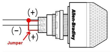
R710
*Only specified modifications
to control system devices permitted. The Driver
Station Software, roboRIO, PDP/PDH, PCM(s)/PH(s), VRM(s)/RPM(s), RSL, 120A
breaker, motor controllers, MXP devices used to control actuators per R713-C, relay modules (per R503-B), wireless
bridge, PDH/PDP breakers and fuses, and batteries shall not be tampered with,
modified, or adjusted in any way (tampering includes drilling, cutting,
machining, rewiring, disassembling, painting, etc.), with the following
exceptions:
Please note that
the Driver Station Software is a separate application from the Dashboard. The Driver
Station Software may
not be modified, while teams are expected to customize their Dashboard code.
A.
User programmable code in the roboRIO may be customized.
B.
Motor controllers may be calibrated as described in owner's manuals.
C.
Fans may be attached to motor controllers and may be powered from the
power input terminals.
D.
If powering the compressor, the fuse on a Spike H-Bridge Relay may be
replaced with a VB3A-20A Snap-Action circuit breaker.
E.
Wires, cables, and signal lines may be connected via the standard
connection points provided on the devices.
F.
Fasteners (including adhesives) may be used to attach the device to the Operator Console or Robot
or to secure cables to the device.
G.
Thermal interface material may be used to improve heat conduction.
H.
Labeling may be applied to indicate device purpose, connectivity,
functional performance, etc.
I.
Jumpers may be changed from their default location.
J.
Limit switch jumpers may be removed from a Jaguar motor controller and a
custom limit switch circuit may be substituted.
K.
Device firmware may be updated with manufacturer supplied firmware.
L.
Integral wires on motor controllers may be cut, stripped, and/or
connectorized.
M.
Devices may be repaired, provided the performance and specifications of
the device after the repair are identical to those before the repair.
N.
The cover may be removed from the Talon SRX data port.
O. Electrical
tape may be applied to the aluminum plate inside the wireless bridge.
P.
The input terminal cover from the PDP may be omitted (no other element
may be installed using the threaded holes to install something in place of the PDP terminal cover).
Q.
The roboRIO 2.0 SD card may be replaced with an SD card of any capacity.
R.
adding insulating material to exposed conductors on PDH/PDP breakers and
fuses.
S.
functional equivalents to CONTROL SYSTEM power terminal blocks.
Please note that
while repairs are permitted, the allowance is independent of any manufacturer’s
warranty. Teams make repairs at their own risk and should assume that any
warranty or return options are forfeited. Be aware that diagnosing and
repairing Components such as these can be
difficult.
For more
information about modification O, please see this
OM5P-AC Radio Modification article.
R711
*Don’t connect motor outputs
to roboRIO. Neither 12VDC power nor relay module or motor controller
outputs shall be directly connected to the roboRIO, with the exception of the
designated 12VDC input.
R712
*Control PWM controllers from
the roboRIO. Every relay module (per R503-B), servo controller, and PWM motor controller shall be
connected to a corresponding port (relays to Relay ports, servo controllers and
PWM controllers to PWM ports) on the roboRIO (either directly or through a WCP
Spartan Sensor Board) or via a legal MXP
connection (per R713). They shall not be controlled by
signals from any other source, with the exception of the Nidec Dynamo motor
controller which must also be connected to the roboRIO Digital I/O.
R713
*Only approved MXP devices can
control actuators. If a motor is controlled
via the MXP, its power regulating device must
be connected by 1 of the following methods:
A. directly
to any PWM pins,
B. via a
network of Passive Conductors used to extend
the PWM pins, or
C. via 1
approved Active Device:
a.
Kauai Labs navX MXP
b. Kauai
Labs navX2 MXP
c. RCAL
MXP Daughterboard
d. REV Robotics RIOduino
e. REV Robotics Digit Board
f. West
Coast Products Spartan Sensor Board
g. Huskie
Robotics HUSKIE 2.0 Board
R714
*Control CAN motor controllers
from the roboRIO. Each CAN motor controller must be controlled with
signal inputs sourced from the roboRIO and passed via either a PWM (wired per R713) or CAN bus (either directly or daisy-chained via another
CAN bus device) signal, but both shall not be wired simultaneously on the same
device.
As long as the CAN
bus is wired legally so that the heartbeat from the roboRIO is maintained, all
closed loop control features of the CAN motor controller may be used. (That is,
commands originating from the roboRIO to configure, enable, and specify an
operating point for all CAN motor controller closed loop modes fit the intent
of R701).
“Wired directly”
includes via any series of passive conductors
(i.e. star or hub configurations using only passive
conductors are permitted.)
R715
*Control PCM/PH(S) from
roboRIO. Each PCM/PH must be controlled with signal inputs sourced from
the roboRIO and passed via a CAN bus connection from the built-in CAN on the roboRIO
(either directly or daisy-chained via another CAN bus device).
R716
*Connect the PDP/PDH to the roboRIO
CAN bus. The PDP/PDH
CAN interface must be connected to the built-in CAN bus on the roboRIO (either
directly or daisy-chained via another CAN bus device).
R717
*Don’t alter the CAN bus.
No device that interferes with, alters, or blocks communications among the
roboRIO and the PDP/PDH, PCMs/PHs, and/or CAN motor controllers on the bus will
be permitted.
Only 1 wire
should be inserted into each Weidmuller CAN connector terminal. For documentation
on how to wire the CAN bus connections see How
to Wire an FRC Robot.
R718
*USB to CAN adapter permitted. Additional CAN bus connections may be added to the
roboRIO using the CTR Electronics CANivoreTM P/N 21-678682
USB-to-CAN adapter.
Any additional
CAN bus added in this manner satisfies the requirements of R714
(i.e. you may connect motor controllers to this additional bus).
In order to maintain safety, the rules in this section apply
at all times while at the event, not just while the Robot
is on the Field for Matches.
R801
*Only use explicitly permitted
pneumatic parts. To satisfy multiple
constraints associated with safety, consistency, inspection, and constructive
innovation, no pneumatic parts other than those explicitly permitted in this
section shall be used on the Robot.
R802
*No custom pneumatics and meet
minimum pressure ratings. All pneumatic
items must be COTS pneumatic devices and either:
A.
rated by their manufacturers for pressure of at least 125psi (~862 kPa)
or
B.
installed downstream of the primary relieving regulator (see R809), and rated for pressure of at least 70psi (~483 kPa)
Any pressure
specification such as “working,” “operating,” “maximum,” etc. may be used to
satisfy the requirements of this rule.
It is recommended
that all pneumatic items be rated by their manufacturers for a working pressure
of at least 60 psi (~414 kPa).
R803
*Don’t modify pneumatics. All pneumatic Components
must be used in their original, unaltered condition. Exceptions are as follows:
A.
tubing may be cut,
B.
wiring for pneumatic devices may be modified to interface with the
control system,
C.
assembling and connecting pneumatic Components
using the pre-existing threads, mounting brackets, quick-connect fittings,
etc.,
D.
removing the mounting pin from a pneumatic cylinder, provided the
cylinder itself is not modified, and
E.
labeling applied to indicate device purpose, connectivity, functional
performance, etc.
Do not, for
example, paint, file, machine, or abrasively remove any part of a pneumatic Component – this would cause the part to become a
prohibited item. Consider pneumatic Components
sacred.
R804
*Only use specific pneumatic
devices. The only pneumatic system items permitted on Robots include the following items:
A.
pneumatic pressure vent plug valves functionally equivalent to those
provided in the KOP,
Examples of
acceptable valves include Parker PV609-2 or MV709-2.
B. pressure relief
valves functionally equivalent to those provided in the KOP,
Examples of
acceptable valves include Norgren 16-004-011, 16-004-003 or McMaster-Carr
48435K714.
To be considered
functionally equivalent the valve must be preset or adjustable to 125 psi (~862
kPA) and capable of relieving at least 1 scfm (~472 cm3/s).
C. solenoid valves
with a maximum ⅛ in. (nominal, ~3 mm) NPT, BSPP, or BSPT port diameter or
integrated quick connect ¼ in. (nominal, ~6mm) outside
diameter tubing connection,
D. additional
pneumatic tubing, with a maximum ¼ in. (nominal, ~6 mm) outside diameter,
E. pressure
transducers, pressure gauges, passive flow control valves (specifically “needle
valve”), manifolds, and connecting fittings (including COTS pneumatic U-tubes),
F. check
and quick exhaust valves, provided that the requirements of R813
are still met.
G. shutoff valves
which relieve downstream pressure to atmosphere when closed (may also be known
as 3-way or 3-way exhausting valves),
H. pressure regulators
with the maximum outlet pressure adjusted to no more than 60 psi (~413 kPa),
I. pneumatic
cylinders, pneumatic linear actuators, and rotary actuators,
J. pneumatic
storage tanks (with the exception of white Clippard tanks P/N AVT-PP-41),
K. 1 compressor
that is compliant with R806,
L. debris
or coalescing (water) filters, and
M. Venturi valves
(note: the high-pressure side of a Venturi valve is considered a pneumatic
device and must follow all pneumatic rules. The vacuum side of a Venturi valve
is exempt from the pneumatic rules per “a” in the blue box below).
The following
devices are not considered pneumatic devices and are not subject to pneumatic
rules (though they must satisfy all other rules):
a. a device that creates a vacuum,
b. closed-loop COTS pneumatic
(gas) shocks,
c. air-filled (pneumatic) wheels, and
d. pneumatic devices not used as part of a pneumatic system
(i.e. used in a way that does not allow them to contain pressurized air)
R805
*If using pneumatics, these
parts are required. If pneumatic Components are used, the following items are required
as part of the pneumatic circuit and must be used in accordance with this
section, as illustrated in Figure 9‑17.
A.
1 FIRST Robotics Competition legal
compressor (per R806),
B.
a pressure relief valve (per R804-B) connected and
calibrated (per R811),
C.
a Nason pressure switch (P/N SM-2B-115R/443) and/or REV Robotics Analog Pressure Sensor (P/N REV-11-1107)
connected and wired per R812,
D.
at least 1 pressure vent plug plumbed (per R813),
E.
stored pressure gauge and working pressure gauge (per R810),
and
F.
1 primary working pressure regulator (per R808).
Figure 9‑17
Pneumatic circuitry
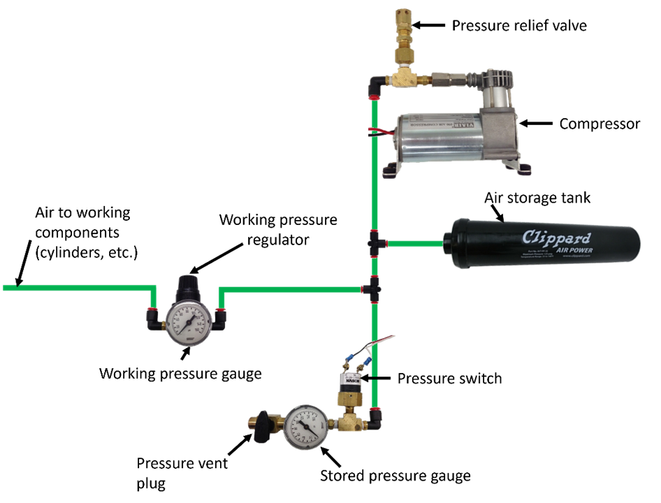
R806
*Compressed air from robot compressor only. Throughout
an event, compressed air on the Robot must be
provided by its 1 onboard compressor only. Compressor specifications must not
exceed nominal 1.1 cfm (~519 cm3/s) flow rate @ 12VDC at any
pressure.
A Robot’s compressor may be substituted by another
compressor, but a Robot may only have 1
designated compressor at a time, and all compressed air on the Robot must be sourced from a single compressor.
Note: Viair
C-series compressors, which have a max working pressure of 120 PSI, are rated
for intermittent pressures greater than 125 PSI and therefore meet the
requirements of this rule.
R807
*Air storage pressure limit. Stored air pressure on the Robot
must be no greater than 120 psi (~827 kPa). No stored air pressure intended for
the Robot may be located off-board the Robot.
R808
*Working air pressure limit. Working air pressure (air pressure used to actuate
devices) on the Robot must be no greater than
60 psi (~413 kPa) and must be provided through a single primary adjustable,
relieving, pressure regulator.
Examples of
acceptable valves include Norgren regulator P/N R07-100-RNEA and Monnier P/N
101-3002-1.
R809
*Limited devices at high
pressure. Only the compressor, relief valve,
pressure switch, pressure vent plug, pressure gauge, storage tanks, tubing,
pressure transducers, filters, and connecting fittings may be in the
high-pressure pneumatic circuit upstream from the regulator.
It is recommended
that all Components in the high-pressure
pneumatic circuit upstream from the regulator be rated for at least 115 psi
(~793 kPa) working pressure.
R810
*Pressure gauges must be
visible. Pressure gauges must be placed in
easily visible locations upstream and downstream of the regulator to display
the stored and working pressures, respectively. Pressure gauges must show
pressure in psi or kPa.
R811
*Relief valve requirements. The relief valve must be attached directly to the
compressor or attached by legal hard fittings (e.g. brass, nylon, etc.)
connected to the compressor output port.
Teams are required to check and/or adjust
the relief valve to release air at 125 psi (~861 kPa). The valve may or may not
have been calibrated prior to being supplied to teams.
Instructions for
adjusting the pressure relief valve can be found in the Pneumatics
Manual.
R812
*Pressure switch requirements. The pressure switch must be
connected to the high-pressure side of the pneumatic circuit (i.e. prior to the
pressure regulator) to sense the stored pressure of the circuit.
It must be either:
A.
Nason P/N SM-2B-115R/443 (wired as described) and/or
The 2 wires from the pressure switch must
be connected directly to the pressure switch input of the PCM/PH controlling
the compressor or, if controlled using the roboRIO and a relay, to the roboRIO.
If connected to the roboRIO, the roboRIO must be programmed to sense the state
of the switch and operate the relay module that powers the compressor to
prevent over-pressuring the system.
B.
REV Robotics P/N REV-11-1107 (wired as described)
The analog output of the sensor must be
connected directly to analog input 0 of the PH (with firmware version 22.0.2 or
newer) controlling the compressor.
The REV Robotics Analog Pressure Sensor may only be used
with PH compressor control and may not be used
with PCM compressor control.
R813
*Vent plug requirements. Any pressure vent plug must be:
A.
connected to the pneumatic circuit such that, when manually operated, it
will vent to the atmosphere to relieve all stored pressure in a reasonable
amount of time and
B.
placed on the Robot so that it is
visible and easily accessible.
R814
*Don’t connect solenoid
outputs together. The outputs from multiple
solenoid valves must not be plumbed together.
R901
*Use the specified Driver
Station Software. The Driver Station Software provided by
National Instruments (install
instructions found here) is the only application permitted to specify and
communicate the operating mode (i.e. AUTO/TELEOP) and operating state (Enable/Disable)
to the Robot. The Driver Station Software must be version 23.1 or newer.
Teams are
permitted to use a portable computing device of their choice (laptop computer,
tablet, etc.) to host the Driver Station Software while participating in Matches.
R902
*The operator console must have a visible display. The Operator Console, the set of Components and Mechanisms used by the Drivers
and/or Human PlayerS to relay commands to the Robot, must include a graphic display to present
the Driver Station Software diagnostic information.
It must be positioned within the Operator Console
so that the screen display can be clearly seen during inspection and in a Match.
R903
*Connect FMS Ethernet directly
to the operator console. Devices hosting the Driver Station Software must only interface with the FMS via the Ethernet cable provided at the Driver Station (e.g. not through a switch). Teams may
connect the FMS Ethernet cable to the device
running the Driver Station Software directly
via an Ethernet pigtail, or with a single-port Ethernet converter (e.g. docking
station, USB-Ethernet converter, Thunderbolt-Ethernet converter, etc.). The Ethernet
port on the Operator Console must be easily and
quickly accessible.
Teams are
strongly encouraged to use pigtails on the Ethernet port used to connect to the
FMS. Such pigtails will reduce wear and tear on
the device’s port and, with proper strain relief employed, will protect the
port from accidental damage.
R904
*Operator console physical requirements. The Operator Console must not
A.
be longer than 5 ft. (~152 cm),
B.
be deeper than 1 ft. 2 in. (~35 cm) (excluding any items that are held
or worn by the Drivers during the Match),
C.
extend more than 6 ft. 6 in. (~198 cm) above the floor, or
D.
attach to the Field (except as permitted
by G301).
There is a 4 ft.
6 in. (~137 cm) long by 2 in. (nominal) wide strip of hook-and-loop tape
(“loop” side) along the center of the Driver Station
support shelf that should be used to secure the Operator
Console to the shelf, per G301. See Section 5.7.1 DRIVER STATIONS for details.
Please note that
while there is no hard weight limit, Operator Consoles
that weigh more than 30 lbs. (~13 kg.) will invite extra scrutiny as they are
likely to present unsafe circumstances.
R905
*Field wireless only. Other
than the system provided by the Field, no other
form of wireless communications shall be used to communicate to, from, or
within the Operator Console.
Examples of
prohibited wireless systems include, but are not limited to, active wireless
network cards and Bluetooth devices. For the case of the FIRST Robotics Competition, a motion sensing input device
(e.g. Microsoft Kinect) is not considered wireless communication and is
allowed.
R906
*No unsafe operator consoles. Operator Consoles shall not be made using hazardous
materials, be unsafe, cause an unsafe condition, or interfere with other drive teams or the operation of other Robots.

10 Inspection & Eligibility
Rules
This section describes the rules governing Match participation. A team has participated in a Match if any member of their drive team is in the Alliance
Area, with or without the Robot on the Field, at the start of the Match.
At each event, the Lead Robot
INSPECTOR (LRI) has final authority on the
legality of any Component, Mechanism, or Robot.
INSPECTORS may re-inspect Robots at any time to
ensure compliance with the rules. Teams are encouraged to consult with
INSPECTORS or the LRI if they have any
questions regarding the legality of a Robot or
about how to make a Robot legal.
The inspection process may progress in blocks, i.e. it may
pause for a team’s Practice MATCH,
slot on the practice field, lunch break, etc. The process may employ various INSPECTORS throughout the process based on
availability. At the team’s discretion, they may request a different INSPECTOR or invite the Lead ROBOT INSPECTOR
to participate in their ROBOT’S
inspection.
While there is no specific defined procedure in place for
teams to be re-inspected prior to Playoff Matches,
it is typical for INSPECTORS to use the re-inspection discretion described
above to do a limited re-inspection on all Robots
near the end of QUALIFICATIONS or beginning of Playoff Matches to help identify any modifications that
should be re-inspected per I104.
Robots are permitted to
participate in scheduled Practice Matches prior
to passing inspection. However, the FTA, LRI, or Head Referee
may determine at any time that the Robot is unsafe
and may prohibit further participation in Practice Matches
until the condition is corrected and/or the Robot
passes inspection.
Prior to the start of a Match,
any Robot which is unable or
ineligible to participate in that Match, as
determined by the FTA, LRI, or Head Referee, is declared to be Bypassed
and is Disabled. A team whose Robot is Bypassed
remains eligible to receive Qualification Ranking Points or Playoff Match points provided that its Robot has passed inspection, per I102.
An Inspection
Checklist is available to help teams self-inspect
their robot before their event. Teams are
strongly encouraged to self-inspect prior to their event.
I101
*It’s your team’s Robot. The Robot and
its Major Mechanisms must be built by the FIRST
Robotics Competition team.
A Major Mechanism
is a group of Components
and/or Mechanisms assembled together to address
at least 1 game challenge: Robot movement, GAME PIECES manipulation, Field
element manipulation, or performance of a scorable task without the assistance
of another Robot.
This rule
requires that the Robot and its Major Mechanisms were built by its team, but isn’t
intended to prohibit or discourage assistance from other teams (e.g.
fabricating elements, supporting construction, writing software, developing game
strategy, contributing Components and/or Mechanisms, etc.)
Examples of Major Mechanisms include, but are not limited to,
assemblies used to:
a. manipulate GAME PIECES,
b. manipulate a Field element,
and
c. move the Robot around the Field.
Examples that
would generally not be considered Major Mechanisms,
and thus probably aren’t subject to this rule include, but are not limited to,
the following:
a. a gearbox assembly,
b. a Component or Mechanism that’s part of a Major
Mechanism, and
c. COTS items.
Neither this rule
nor the language in this blue box define specific thresholds for how much of a Major Mechanism must be the result of the team’s
effort. This rule expects and requires the team’s honest assessment of whether
they built the Major Mechanisms of their Robot.
Attempts to
exploit loopholes in the definition of Major Mechanism
in order to bypass this requirement are in the spirit of neither this rule nor
the FIRST Robotics Competition. Examples
of exploitation include:
a. assembling pieces of a Major
Mechanism provided by another team, except COTS
kits and
b. receiving a mostly complete Major
Mechanism from another team and providing a small piece.
I102
*Get inspected before playing
a Qualification/Playoff Match. A team is only permitted to participate in a Qualification
or Playoff Match and receive Ranking or Match Points if their Robot
has passed an initial, complete inspection.
Violation: If prior to the start of the Match, the team is Disqualified
and not eligible to participate in the Match.
If after the start of the Match, the
entire Alliance receives a Red Card for that Match.
Please take note
of this rule. It is important that FIRST Robotics
Competition teams ensure their Alliance
partners have passed inspection. Allowing a partner that has not passed inspection
to play puts the Alliance at risk of Red Cards. Teams should check with their Alliance partners early and help them pass inspection
before competing.
I103
*Bring it all to inspection.
At the time of inspection, the Operator Console
and the Robot must be presented with all Mechanisms (including all Components
of each Mechanism), configurations, and
decorations that will be used on the Robot in Matches without re-inspection (per I104)
and may not exceed 150 lbs. (~68 kg) (note that while up to 150 lbs. (~68 kg) of
Robot Mechanisms
may be inspected together, the Robot
configuration used in a Match may not violate R103). The Operator Console
and exceptions listed in R103 are not included in this
weight.
I104
*Unless the change is listed
below, any change to a Robot must get re-inspected. A Robot may play Matches
with a subset of the Mechanisms that were
present during inspection provided the reconfigured Robot
still complies with all Robot Construction
Rules. Only Mechanisms that were present during
the inspection may be added, removed, or reconfigured between Matches without re-inspection per this rule. If a Robot is modified after its most recent passed inspection,
it must be re-inspected before it is eligible to participate in a Match. A Robot that
plays in a Match with an un-inspected
modification may be retro-actively disqualified
at the discretion of the LRI and Head Referee.
Exceptions are listed in A
through F (unless they result in a significant change to
the Robot’s size, weight, legality, or safety).
A. addition,
relocation, or removal of fasteners (e.g. cable ties, tape, and rivets),
B.
addition, relocation, or removal of labeling or marking,
C.
revision of Robot code,
D.
replacement of a COTS Component with an identical COTS
Component,
E.
replacement of a Mechanism with an
identical Mechanism (size, weight, material),
and
F. additions,
removals, or reconfiguration of Robot with a
subset of Mechanisms already inspected per I103.
I105
*Don’t exploit re-inspection. Teams may not use the re-inspection process in I104 to circumvent the weight limit in I103.
This restriction
is not intended to prevent a team from returning to a previous configuration
(e.g. due to an unsuccessful upgrade or failure of a new Component). If a team is believed to be violating
this rule, the LRI will discuss the situation
with the team to understand the changes and, if appropriate, the LRI in conjunction with the team will select a single
configuration with which the team will compete for the duration of the event.
Example 1: A Robot passes initial inspection (which includes Mechanism A). Its team then decides they want to use Mechanism B, which was not inspected. The weight of
the Robot, A, and B is less than the weight
limit in I103, but more
than that in R103. I104 requires the Robot be re-inspected, and this rule allows the Robot, A, and B to be inspected collectively. If
passed, the Robot may then compete in
subsequent matches with A or B.
Example 2: A Robot passes initial inspection (which includes Mechanism A). Its team then decides they want to use Mechanism B, which was not inspected. The weight of
the Robot, A, and B is greater than the weight
limit in I103. This
requires re-inspection per I104 and A is excluded to satisfy I103. B breaks, and the team decides to switch back to A. The Robot must be re-inspected per I104, and the team is not violating this rule.
Example 3: A team
arrives at an event with a Robot, Mechanism A, and Mechanism
B, which collectively weigh 175 lbs (79 kg). The Robot
passes initial inspection with A and plays a Match.
The team switches to B, gets re-inspected, and plays again. The team switches
back to A, gets re-inspected, and plays again. The team switches back to B and
asks to be re-inspected. At this point, the LRI
suspects the team may be violating this rule and has a discussion with the team
to understand the changes being made. The team reveals that this rule has been
violated, and the LRI works with them to select
A or B for use for the remainder of the event.
I106
*Robots are off for inspection (mostly). For the
safety of all those involved, Robots, must be
presented for inspection with the Robot powered
off, pneumatics unpressurized, and springs or other stored energy devices in
their lowest potential energy states (e.g. battery removed).
Power and air pressure should only be
enabled on the Robot during those portions of
the inspection process where it is absolutely required to validate certain
system functionality and compliance with specific rules (firmware check, etc.).
INSPECTORS may allow the Robot to be powered
beyond the parameters above if both criteria below are met:
A.
the Robot design requires power or a
charged stored energy device in order to confirm that the Robot meets volume requirements and
B.
the team has included safety interlocks that mitigate unexpected release
of such stored energy.
The team may be
asked to demonstrate these interlocks during the inspection process.
I107
*No student, no inspection. At least 1 student team member must accompany the Robot for any inspection efforts.
Exceptions may be
made for major conflicts, e.g. religious holidays, major testing,
transportation issues, etc.
11 Tournaments
Each
2023 FIRST® Robotics Competition event is played in a
tournament format. Each tournament consists of 3 types of Matches: Practice Matches
(not necessarily played at all District Events), Qualification Matches, and Playoff Matches.
Practice Matches provide
each team with an opportunity to operate its Robot
on the Field prior to the start of the
Qualification Matches.
Qualification Matches allow
each team to earn Ranking Points which determine their seeding position and may
qualify them for participation in the Playoff Matches.
Playoff Matches determine
the event Champions.
A Match schedule is used to
coordinate Matches at an Event. Figure 11‑1 details information shown on each schedule. Surrogate matches are described in Section 11.6.2 MATCH Assignment.
Figure
11‑1 Sample Match schedule
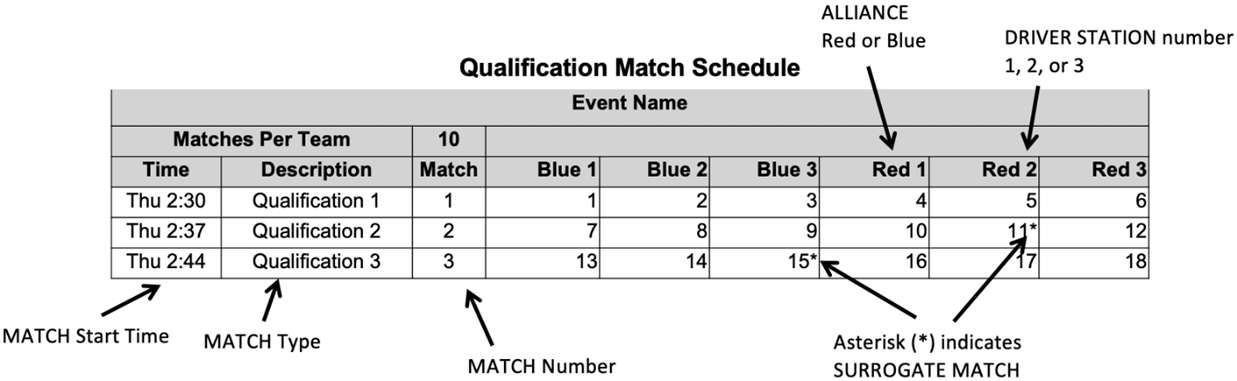
11.2 Head REFEREE and FTA Interaction
The Head Referee has the
ultimate authority in the Arena during the
event, but may receive input from additional sources, e.g. Game Designers, FIRST
personnel, FTA, and other event staff. The Head Referee
rulings are final. No event staff, including the Head Referee,
will review video, photos, artistic renderings, etc. of any Match, from any source, under any circumstances.
Each ALLIANCE has a designated Question Box near the scoring
table. If a DRIVE TEAM has a question about a MATCH, the FIELD, etc., they may
send 1 DRIVE TEAM member to their corresponding Question Box. Depending on
timing, the Head Referee or FTA may postpone any requested discussion
until the end of the subsequent MATCH as necessary.
Technical questions regarding FIELD or ROBOT operation are
addressed by the FTA, additional team members are invited to participate in these
conversations if necessary. If a DRIVE TEAM needs clarification on a
ruling or score, per H202, 1 STUDENT from that DRIVE TEAM should address the
Head REFEREE after the Arena Reset Signal (e.g.
Field lights turn green).
While FMS tracks quantities of Fouls,
FIRST instructs Referees to not self-track
details about Fouls and Tech Fouls; as a result, we don’t expect Referees to recall details about what Fouls and Tech Fouls
were made, when they occurred, and against whom.
Any reasonable
question is fair game in the Question Box, and Head Referees
will make good faith efforts to provide helpful feedback (e.g. how/why certain Fouls are being called, why a particular Robot may be susceptible to certain Fouls based on its design or game play, how specific
rules are being called or interpreted), but please know that they may not be
able to supply specific details.
11.2.2
YELLOW and RED
CARDS
In addition to rule violations explicitly listed throughout
the 2023 Game Manual, Yellow Cards and Red Cards are used in FIRST Robotics Competition to address team and Robot behavior that does not align with the mission,
values, and culture of FIRST.
As noted in Section 6.5 Rule
Violations and H201, the Head Referee
may assign a Yellow Card as a warning, or a Red Card for DISQUALIFICATION in Match for egregious behavior inappropriate at a FIRST
Robotics Competition event.
A YELLOW or Red Card is
indicated by the Head Referee holding a YELLOW
and/or Red Card in the air while the Game
Announcer describes the violation.
Per Section 6.5 Rule
Violations Yellow Cards are additive,
meaning that a second Yellow Card is automatically
converted to a Red Card. A team is issued a Red Card for any subsequent incident in which they
receive an additional Yellow Card, including
earning a second Yellow Card during a single Match. A second Yellow Card
is indicated by the Head Referee holding a Yellow Card and Red Card
in the air simultaneously after the completion of the Match.
A team that has received either a Yellow Card
or a Red Card carries a Yellow Card into subsequent Matches,
except as noted below.
Once a team receives a yellow
or Red Card, its team number is presented with
a yellow background on the audience screen at the beginning of all subsequent Matches, including any replays, as a reminder to the
team, the Referees, and the audience that they
carry a Yellow Card.
Figure 11‑2
Example audience screen graphic showing Yellow Card
indicators
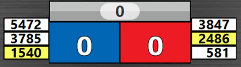
All Yellow Cards are cleared
in FMS at the conclusion of Practice,
Qualification, and division Playoff Matches. Verbal
warnings are cleared after Practice MATCHES and persist from Qualification
MATCHES through subsequent tournament phases. The Head Referee may opt to perpetuate a verbal warning or Yellow Card earned during Practice Matches through to Qualification Matches for particularly egregious behavior.
yellow and Red Cards are applied based on the following:
Table 11‑1 yellow
and Red Card application
|
Time YELLOW or RED CARDS earned:
|
MATCH to which CARD is applied:
|
|
prior to Practice MATCHES
|
Team’s first Practice MATCH
|
|
during the
Practice Matches
|
Team’s current (or just-completed) Match.
|
|
between the end of PRACTICE
MATCHES and the start of Qualification Matches
|
Team’s
first Qualification Match
|
|
during
the Qualification Matches
|
Team’s current (or just-completed) Match. In the case where the
team participated as a Surrogate in the current (or just completed) Match, the card is applied
to the team’s previous Match (i.e. the team’s second Qualification
Match)
|
|
between the end of Qualification Matches and the start of Playoff Matches
|
Alliance’s first Playoff Match
|
|
during
the Playoff Matches
|
Alliance’s current (or
just-completed) Match
|
During Playoff Matches, yellow and Red Cards are
assigned to the violating team’s entire Alliance
instead of to only the violating team. If an alliance
receives 2 Yellow Cards, the entire Alliance is issued a Red
Card which results in DISQUALIFICATION for the associated Match. If both Alliances
receive a Red Card, the Alliance assessed the first Red
Card, chronologically, is DISQUALIFIED and loses the MATCH.
Over the course of the tournament, it may be necessary for a
Match to be replayed. Typical causes for
replays are Matches that end in a tie during
the Playoffs, Matches that are stopped because Field Staff anticipated Field
damage or personal injury, or if there is an Arena
Fault. An Arena Fault is an error in Arena operation
that includes, but is not limited to:
A.
broken Field elements due to
a. normal,
expected game play or
b. Robot abuse of Field
elements that affects the outcome of the Match
for their opponents,
A broken Field element caused by Robot
abuse that affects the outcome of the Match for
their Alliance is not an Arena Fault.
B.
power failure to a portion of the Field
(tripping the circuit breaker in the Driver Station
is not considered a power failure),
C.
improper activation by the FMS, and
D.
errors by Field Staff (except those listed
in Other Logistics).
If, in the judgment of the Head Referee,
an Arena Fault occurs that affects the outcome
of the Match and any team on the affected Alliance desires a replay, the Match will be replayed. FIRST Headquarters
reserves the right to, with consultation of the Head REFEREE and the FTA,
replay a MATCH in which an ARENA FAULT impacts the outcome of an event.
The outcome of
the Match is affected if an error occurs that,
in the judgement of the Head Referee, changes
which Alliance would have won the Match and/or the assignment of Ranking Points.
The outcome of an
event is affected if an error occurs that, in the judgement of FIRST
Headquarters, changes the assignment of Ranking Points or has a dramatic effect
on points used for ranking criteria.
Note that an Arena Fault that does
not affect Match outcome, in the judgement of
the Head Referee, does not lead to a Match replay. Examples include, but are not limited
to:
a. a piece of Field plastic
falls into the Field, far away from any human
or Robot activity, and in such a way that it
does not affect Match outcome,
b. delay in the playing of an Arena
sound,
c. mismatch between the timer on the audience screen and the Arena timer, and
d. any adjustment or delay in assignment of a penalty
(including those made after the Match).
T301
*Replays will be the same.
All reasonable effort is made to create the same conditions when replaying a Match caused by an ARENA FAULT or FIELD damage. This
means, for example, that a team that was Bypassed
prior to the start of the Match which is to be
replayed is Bypassed for the replay Match. Robot and drive team starting locations do not need to be
replicated when replaying a Match.
Violation: MATCH with not start until the situation is
corrected
At each event, the Arena
will be open for at least 30 minutes prior to the start of Qualification Matches, during which time teams may survey and/or
measure the Arena and bring Robots on the Field
to perform sensor calibration. The specific time that the Field is open will be communicated to teams at the
event. Teams may bring specific questions or comments to the FTA.
T401 *Freeze, Robot. During
the period when the Arena is open for
measurement, Robots can be enabled, but may
neither drive, extend outside their FRAME PERIMETER, nor interact with (e.g. score,
push, pickup, etc.) GAME PIECES, the CHARGE STATION, GRIDS, or other Field elements.
Violation: Verbal warning. If subsequent violations at any
point during the event or egregious Yellow Card.
Practice Matches are played
before Qualification MatchES. The Practice Match
schedule is available as soon as possible, but no later than the start of
Practice Matches. For Regional events, it will
also be published and available online at the FIRST Robotics Event
Results site, except during exceptional
circumstances. Practice Matches are randomly
assigned, and teams may not switch scheduled Practice Matches.
Each team is assigned an equal number of Practice Matches
unless the number of teams multiplied by number of Practice Matches is not divisible by 6. In this case, the FMS randomly selects some teams to play an extra
Practice Match.
Practice Matches are not guaranteed
at District Events due to event schedule constraints.
A Filler Line is used to fill open slots at events that
employ scheduled Practice Matches or all slots
at events with an open Practice Match schedule.
Teams from the Filler Line are used on a first come, first served basis to fill
empty spots in Practice Matches left by other
teams that do not report to Queueing. The number of teams in the Filler Line is
dependent upon space at venues.
Only teams that meet all criteria below qualify for the
Filler Line:
A.
Robots in the Filler Line must have
passed inspection (this requirement may be waived for events with open Practice
Match schedules),
B.
Drive teams must join the Filler Line
with their Robot,
C.
teams may not work on their Robot while
in the Filler Line,
D.
teams may not occupy more than 1 spot in the Filler Line, and
E.
if a team is queued for their Practice Match,
they may not also join the Filler Line.
11.6
Qualification MATCHES
The Qualification Match
schedule is made available as soon as possible, but no later than 30 minutes
before Qualification MatchES are scheduled to
begin. Teams receive 1 hard copy and it is also available at the FIRST Robotics Competition Event
Results site, except during exceptional
circumstances. Each Qualification schedule consists of a series of rounds in
which each team plays 1 Match per round.
FMS assigns each team 2 Alliance partners for each Qualification Match using a predefined algorithm, and teams may not
switch Qualification Match assignments. The
algorithm employs the following criteria, listed in order of priority:
1. maximize
time between each Match played for all teams
2. minimize
the number of times a team is allied with any team
3. minimize
the number of times a team plays opposite any team
4. minimize
the use of Surrogates (teams randomly assigned
by the FMS to play an extra Qualification Match)
5. provide
even distribution of Matches played on blue and
red Alliance
6. provide
even distribution of Matches played in each Driver Station number
At events with fewer than 24 participating teams, the
criteria are similar, however criterion 5 is changed to minimize the number of
times a team swaps between the blue and red alliance
rather than an even distribution.
All teams are assigned the same number of Qualification Matches, equal to the number of rounds, unless the
number of teams multiplied by number of Matches
is not divisible by 6. In this case, the FMS
randomly selects some teams to play an extra Match.
For the purpose of seeding calculations, those teams are designated as Surrogates for the extra Match.
If a team plays a Match as a Surrogate, it is indicated on the Match schedule, it is always their third Qualification
Match, and the outcome of the Match has no effect on the team’s ranking. yellow and Red Cards
assigned to Surrogates, however, do carry
forward to subsequent Matches.
Ranking Points are units credited to a team based on their Alliance’s performance in Qualification Matches. Ranking Points are awarded to each eligible
team at the completion of each Qualification Match
per Table 6‑2.
Exceptions to Ranking Point assignment are as follows:
A.
A Surrogate receives 0 Ranking Points.
B.
A Disqualified team, as determined by
the Head Referee, receives 0 Ranking Points in
a Qualification Match or causes their Alliance to receive 0 Match
points in a Playoff Match.
C.
A “no-show” team is either Disqualified
from or issued a Red Card for that Match (see H305). A team is
declared a no-show if no member of the drive team
is in the Alliance Area at the start of the Match.
The total number of Ranking Points earned by a team
throughout their Qualification Matches divided
by the number of Matches they’ve been scheduled
to play (minus any Surrogate Match), then truncated to 2 decimal places, is their
Ranking Score (RS).
All teams participating in Qualification Matches are ranked by Ranking Score. If the number of
teams in attendance is ‘n’, they are ranked ‘1’ through ‘n’, with ‘1’ being the
team with the highest Ranking Score and ‘n’ being the team with the lowest
Ranking Score.
Teams are ranked in order, using the sorting criteria
defined in Table 11‑2.
Table 11‑2 Qualification Match ranking criteria
|
Order
Sort
|
Criteria
|
|
1st
|
Ranking Score
|
|
2nd
|
Average
Alliance Match
points, not including Fouls
|
|
3rd
|
Average Alliance CHARGE STATION points
|
|
4th
|
Average
Alliance Auto
points
|
|
5th
|
Random sorting by the FMS
|
Playoff matches follow the
qualification matches. In the Playoffs, teams
play on set alliances, chosen during alliance selection, and advance through a double
elimination bracket. Teams do not earn Ranking Points; they advance based on
winning, losing, or tying a match.
11.7.1
ALLIANCE Selection Process
At the end of the
Qualification Matches, the top 8 ranked teams become
the Alliance Leads. The ranked Alliances are designated, in order, Alliance 1, Alliance 2,
etc., down to Alliance 8. Using the Alliance selection process described in this section,
each Alliance Lead chooses 2 other teams to
join their Alliance.
T701
*Send a STUDENT
representative. Each team must choose and send a student team representative to the Arena at the designated Alliance
Selection time (typically before the lunch break on the final day of the event)
to represent their team. The designated student representative from each Alliance Lead is called the Alliance Captain. This
representative may change between alliance selection
and playoff matches.
Violation: Team is ineligible for the Playoff Tournament
If an absent team
would have been an Alliance Lead, all lower
ranked Alliance Leads are promoted 1 spot. The
next highest-ranked team moves up to become the Alliance
8 Lead.
The Alliance selection
process consists of 2 rounds during which each Alliance
Captain invites a team ranked below them in the
standings to join their Alliance.
Round 1: In descending order (Alliance
1 to Alliance 8), each Alliance Captain
invites a single team to join their alliance.
The invited team’s representative steps forward and either accepts or declines
the invitation.
If the team accepts, it becomes a member of that Alliance. If an invitation from a top 8 Alliance to another Alliance
Lead is accepted, all lower Alliance Leads are
promoted 1 spot. The highest-ranked, unselected team becomes the Alliance 8 Lead.
Round 2: The same method is used for each Alliance Captain’s
second choice except the selection order is reversed, with Alliance 8 picking first and Alliance 1 picking last. This process results in 8 Alliances of 3 teams.
T702
*Declining teams can’t be
picked. An ALLIANCE CAPTAIN may not invite a team that has declined
another ALLIANCE’S invitation to participate in the Playoff tournament.
Declining teams are ineligible to be a BACKUP TEAM.
Violation: The ALLIANCE CAPTAIN must make another selection
An ALLIANCE Lead that declines an invitation from
another ALLIANCE is able to invite teams to
join their ALLIANCE but may not be invited to
join another alliance.
At the conclusion of Alliance
selection, the highest ranked unselected teams are eligible to become a Backup Team, as defined in Section
11.7.3 BACKUP TEAMS.
The double elimination
tournament consists of an Upper and Lower bracket as shown in Figure 11‑3. Each Alliance begins with a
slot in the Upper bracket. If an Alliance wins a Match in the Upper bracket, they remain in the Upper
bracket. If an alliance loses a Match in the Upper bracket, they transition to the Lower
bracket. Alliances in the Lower bracket must win any subsequent matches (except for finals) to remain in the tournament, i.e. once they lose a match, they’re out of
the tournament.
In Round 1, the higher ranked
ALLIANCE is assigned to the red ALLIANCE. For subsequent rounds, ALLIANCE color
is assigned as shown in Figure
11‑3, regardless of ALLIANCE rank at the
start of the Playoff tournament.
Figure 11‑3 Playoff MATCH bracket (Red ALLIANCE
tops each pairing)
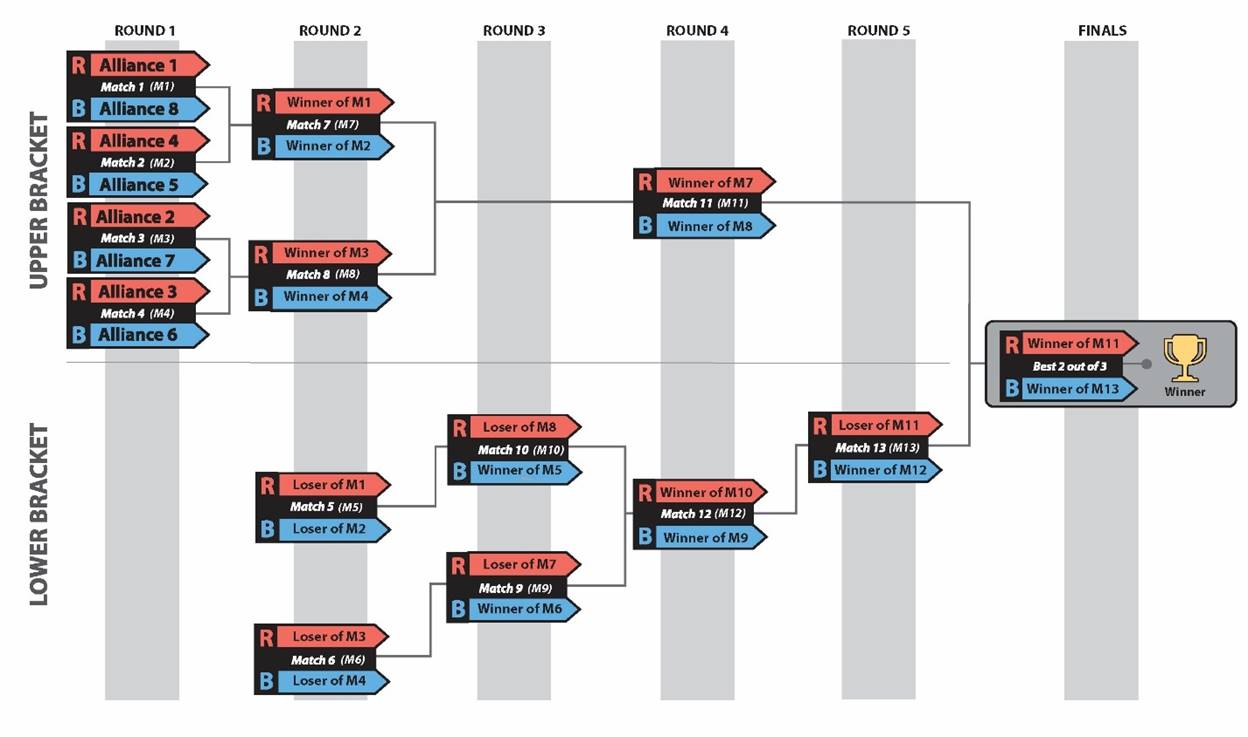
As shown in Figure
11‑3 and Table 11‑3, Playoff Matches
consist of 6 rounds with breaks between rounds and between the Finals Matches. Breaks begin after the field has been cleared from the previous match. The Blue and Red Gap columns indicate the
approximate time between each ALLIANCE’S matches.
The expected start time of the scheduled match
is the time indicated on the match schedule or
15 minutes from the end of either alliance’s
previous match, whichever is later.
If a Playoff MATCH needs to
be replayed as described in Section 11.3 MATCH
Replays, teams are notified of when the replay will occur. A minimum
10-minute delay is provided for teams to reset their ROBOTS prior to the replay
unless all teams are ready sooner. The affected MATCH must be replayed before
the next round begins.
Table 11‑3 Typical Playoff MATCH Schedule
|
Match
|
Blue
|
Red
|
Blue
Gap (minutes)
|
Red
Gap (minutes)
|
Winner
moves to
|
Loser
moves to
|
|
Upper Bracket – Round 1 – Match 1
|
Alliance 8
|
Alliance 1
|
|
|
Red – Match
7
|
Red – Match
5
|
|
Upper Bracket – Round 1 – Match
2
|
Alliance 5
|
Alliance 4
|
|
|
Blue – Match 7
|
Blue – Match 5
|
|
Upper Bracket – Round 1 – Match 3
|
Alliance 7
|
Alliance 2
|
|
|
Red – Match 8
|
Red – Match 6
|
|
Upper Bracket – Round 1 – Match
4
|
Alliance 6
|
Alliance 3
|
|
|
Blue – Match 8
|
Blue – Match 6
|
|
8-minute Break
|
|
Lower Bracket – Round 2 – Match 5
|
Loser of Match 2
|
Loser of Match 1
|
24m
|
31m
|
Blue – Match 10
|
|
|
Lower Bracket – Round 2 - Match
6
|
Loser
of Match 4
|
Loser
of Match 3
|
17m
|
24m
|
Blue – Match 9
|
|
|
Upper Bracket – Round 2 - Match 7
|
Winner of Match 2
|
Winner of Match 1
|
38m
|
45m
|
Red – Match 11
|
Red – Match 9
|
|
Upper Bracket – Round 2 - Match
8
|
Winner
of Match 4
|
Winner
of Match 3
|
31m
|
38m
|
Blue – Match 11
|
Red – Match 10
|
|
8-minute Break
|
|
Lower Bracket – Round 3 - Match 9
|
Winner of Match 6
|
Loser of Match 7
|
24m
|
17m
|
Blue – Match 12
|
|
|
Lower Bracket – Round 3 - Match
10
|
Winner of Match 5
|
Loser of Match 8
|
38m
|
17m
|
Red – Match 12
|
|
|
8-minute Break
|
|
Upper Bracket – Round 4 - Match 11
|
Winner of Match 8
|
Winner of Match 7
|
30m
|
37m
|
Red – Match 14
|
Red – Match 13
|
|
Lower Bracket – Round 4 - Match
12
|
Winner of Match 9
|
Winner of Match 10
|
24m
|
17m
|
Blue – Match 13
|
|
|
15-minute Awards Break
|
|
Lower Bracket – Round 5 - Match 13
|
Winner of Match 12
|
Loser of Match 11
|
17m
|
24m
|
Blue – Match 14
|
|
|
15-minute Awards Break
|
|
Finals – Match 14
|
Winner of Match 13
|
Winner of Match 11
|
17m
|
44m
|
Match 15
|
Match 15
|
|
15-minute
Awards Break
|
|
Finals – Match 15
|
Winner of Match 13
|
Winner of Match 11
|
17m
|
17m
|
Match 16*
|
Match 16*
|
|
15-minute Awards Break *
|
|
Finals – Match 16 *
|
Winner of Match 13
|
Winner of Match 11
|
17m
|
17m
|
|
|
* if required
11.7.2.1
Playoff MATCH ties
If final Match scores for
both Alliances are equal, the win is awarded to
the Alliance per criteria listed in Table 11‑4.
Table 11‑4
Playoff MATCH Tiebreaker Criteria
|
Order
Sort
|
Criteria
|
|
1st
|
Cumulative Tech Foul points due to opponent rule violations
|
|
2nd
|
Alliance CHARGE STATION points
|
|
3rd
|
Alliance AUTO points
|
|
4th
|
Match is replayed
|
11.7.2.2
Playoff Finals
Once a single alliance remains in each Upper and Lower bracket, those Alliances proceed to
the Finals round. The first Alliance to win 2 Matches in the Finals becomes the event’s Champions.
If a Finals match ends in a
tie score, the tie is not broken using the criteria in Table 11‑4, the match remains a tie. In the case where an Alliance hasn’t won 2 Matches
after 3 Matches have been played (because of
tied matches), the Playoffs proceed with up to
3 additional Finals Matches, called Overtime Matches, until an Alliance
has won 2 Finals Matches. In the case where the
Overtime Match scores for both Alliances are equal, the win for that Overtime Match is awarded based on the criteria listed in Table 11‑4.
During the Playoff Matches an Alliance
may elect to replace one of its robots due to a mechanical or software issue that prevents
that robot
from competing effectively. The team whose robot and drive team replaces another robot and drive team on an alliance during the Playoff matches is called the backup team.
In this situation, the Alliance
Captain has the option to bring in the highest
ranked team from the pool of available teams to join its Alliance for the
following match. The resulting Alliance is then
composed of 4 teams.
Alliances submit Lineups (as described in Section
11.7.4 LINEUPS) for each Playoff Match. After the Backup
Team’s first Playoff match, the Alliance’s Lineup may
consist of any 3 of the alliance’s 4 teams.
11.7.3.1
BACKUP TEAM Coupons
Each Alliance is allotted 1 Backup Team coupon during the Playoff Matches. If a second Robot
from the Alliance becomes inoperable, then the Alliance must play the following Matches with only 2 (or even 1) Robots.
Example: 3 teams,
A, B and C, form an Alliance going into the
Playoff Matches. The highest ranked team not on
1 of the 8 Alliances is Team D. During 1 of the
Playoff Matches, Team C’s Robot suffers damage to its mechanical arm. The Alliance Captain
decides to bring in Team D to replace Team C
in the next match. The new Alliance of Teams A, B, C, and D are successful in
advancing to the Finals and win the event. Teams A, B, C, and D are all
recognized as members of the Winning Alliance
and receive awards.
The Head Referee will not
accept the Backup Team coupon unless it lists
the number of the team whose ROBOT is being replaced and is initialed by the Alliance Captain.
Once a Backup Team coupon is submitted and
accepted by the Head Referee, the Backup Team coupon may not be withdrawn by the Alliance.
T703
*No backup Team
for replayed matches. An Alliance may not request a Backup
Team for a replayed Match. The sole
exception is if, in the judgment of the Head Referee,
the replay is due to an Arena Fault that rendered an Alliance’s
Robot inoperable.
Violation: The request
is denied.
T704
*No backup Teams for 1st match. An
Alliance may not request a backup team until after their first Playoff match.
Violation: The request is denied.
T705
*Backup Teams play when called. A
Backup team must be included in the lineup for the alliance’s
next match following their recruitment.
Violation: The lineup
is denied.
If the Head REFEREE
is busy, and there is no designee, the ALLIANCE CAPTAIN remains in the Question
Box to report the Lineup.
T706
*Backup Teams due 2 minutes before
the match start time. The Backup Team Coupon must be submitted
to the Head Referee (or their designee) 2
minutes before the expected match start time in
which the backup team is to
play.
Violation: The request is denied
If the Head REFEREE
is busy, and there is no designee, the ALLIANCE CAPTAIN remains in the Question
Box to submit the BACKUP TEAM coupon.
11.7.3.2
BACKUP POOL
After the top ranked ALLIANCE
has made their final pick during Alliance Selection, REFEREES poll the remaining eligible
teams. In rank order, REFEREES invite remaining teams to accept or decline a
position in the backup pool, i.e. the group of teams
willing and able to join an alliance during the Playoff MATCHES, if needed, until up to 8
teams accept.
T707
*Be there to be a Backup Team. A team must
be present after alliance Selection to accept
the REFEREE’S invitation to join the backup pool.
Violation: Team is ineligible to be a Backup team.
T708
*Send a Backup Team Representative. The top 2 ranked backup teams must send at least 1 student representative (and optionally 1 additional student or mentor) to a designated area near the field for the duration of the Playoff Matches.
These 2 representatives
are available to answer questions and accept invitations to be a BACKUP TEAM from
ALLIANCE CAPTAINS. If 1 of these 2 teams joins
an Alliance or excuses themselves from the backup
pool, the next highest ranked team in the
BACKUP POOL must provide their representative. Once a BACKUP TEAM has
declined an invitation to join an ALLIANCE, it is no longer a member of the BACKUP POOL and ineligible
to join another ALLIANCE.
Violation: Verbal warning. If situation cannot be corrected
within a reasonable amount of time, the team is removed from BACKUP POOL.
Some events may
offer an area near the field where the top 1 or
2 teams in the BACKUP POOL may choose to stage their robot
for quick and easy access to the Field if
recruited.
Each Alliance competing in
a Playoff Match has the option to submit a Lineup, which lists the 3 teams participating in the Match and their
selected DRIVER STATIONS.
The Lineup is kept
confidential until the Field is set for the Match at which point each Alliance’s
Lineup appears on the Team Signs.
If an Alliance has 4 members
(either because a 3-team Alliance has called a backup
team or the event is the FIRST
Championship), a single representative from the team not on the Lineup is allowed as a
sixteenth Alliance member but must be a member of that team’s drive team.
This additional representative may only serve as a COACH.
11.7.4.2
Default LINEUP
T709
*Lineups due 2 minutes before the match. The Alliance Captain must submit their Lineup
in writing to the Head Referee (or their designee) 2 minutes
before their expected match start time.
Violation: Late Lineups
are denied, and the Alliance’s
most recent lineup is applied.
If the Head REFEREE
is busy, and there is no designee, the ALLIANCE CAPTAIN remains in the Question
Box to report the Lineup.
If no previous LINEUP exists, the Alliance Lead
is assigned DRIVER STATION 2, 1st team selected is assigned DRIVER
STATION 1, and the 2nd team selected is assigned DRIVER STATION 3.
If any of these 3 Robots are unable to play,
the Alliance must play the Match with only 2 (or even 1) Robot(s).
Example: 3 teams, A, B, and C form an Alliance
going into the Playoff Matches. During one of the
Playoff Matches, Team C’s Robot becomes inoperable. The Alliance decides to bring in Team D to replace Team
C. Team C repairs their Robot and may play in
any subsequent Playoff Matches replacing Team
A, B, or D
If a BACKUP TEAM
Coupon is accepted and the LINEUP for the next MATCH is not submitted or it
omits the BACKUP TEAM, then the ALLIANCE’S most recent LINEUP is used with the
BACKUP team in the position populated by the team for whom they’re
substituting.
T710
*For replays, no changing Lineups (mostly). If a MATCH must be replayed due to
an ARENA FAULT, the Lineup for the replayed
MATCH is the same as the original MATCH. The sole exception is if the ARENA
FAULT rendered a ROBOT inoperable, in which case the Lineup
can be changed.
Violation: The new Lineup
is denied.
During the Playoff Matches
and because of the distance between the Field
and the pit area, extra team members may be needed to maintain the Robot between Matches.
Each team is permitted to have up to 3 additional pit crew members to help with
needed Robot repairs/maintenance.
The scheduling algorithm described in Section 11.6.2 MATCH Assignment works to minimize
teams playing in back-to-back matches. However,
at events with fewer than 24 teams, back-to-back plays may occur.
Multi-day events with 24 teams or fewer employ a modified
Playoff Match format. Instead of 8 Alliances, these events proceed through Alliance SELECTION and the Playoff Tournament with the
maximum number of complete 3-team Alliances
that can be formed while leaving at least 1 Backup
Team (e.g. a 24-team event creates 7 Alliances,
a 20-team event creates 6 Alliances).

The Playoff Bracket remains as shown in Figure
11‑3, with any matchup against a non-existent Alliance
resulting in a bye (i.e. automatic advancement to the next round). An ALLIANCE
assigned a bye-MATCH is invited, though not required, to practice together in a
null MATCH (i.e. it has no bearing on the
Playoff tournament) during the designated time in the Playoff schedule.
District points for Draft Order Acceptance (per Section 11.8.1.2 ALLIANCE Selection Results)
are awarded as if a full set of Alliances was
selected (i.e. the second selection of the 3-seed Alliance
still receive 3 points regardless of how many Alliances
are formed).
Teams advance through the season depending on the events at
which they compete: Regional or District. This section details how District
teams advance from District qualifying events, to their District Championship.
District teams are ranked
throughout the season based on the points they earn at their first 2 home
District events they attend, as well as at their District Championship. Points
are awarded to teams as follows:
Table 11‑5
District Point Assignment
|
Category
|
Points
|
|
Qualification Round Performance
|

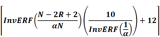
(For a typically sized
District event, this will result in a minimum of 4 points being awarded for
Qualification round performance. For events of all sizes, a maximum of 22
points will be awarded.)
|
|
Alliance
Captains
|
Equal
to 17 minus the Alliance Captain number (e.g.
14 points for Alliance #3 Captain)
|
|
Draft
Order Acceptance
|
Equal to 17 minus the Draft Order Acceptance Number (e.g.
12 points for the team that is fifth to accept an invitation)
|
|
Playoff Advancement
|
Points
awarded based on team participation in individual playoff rounds, and whether
or not the Alliance advances. See Section 11.8.1.3 Playoff Performance for
details.
|
|
Judged
Team Awards
|
10 points for FIRST Impact Award (formerly the Chairman’s
Award)
8 points each for Engineering Inspiration and Rookie All
Star Awards
5 points each for all other judged team awards
|
|
Team Age
|
10
points for 2023 rookie teams
5
points for 2021 and 2022 rookie teams
|
Points earned at District Championships are multiplied by 3
and then added to points earned at District events, to determine the final
season point total for the team.
If there is a tie in the season point total between teams,
those items are broken using the following sorting criteria:
Table 11‑6 District team sort criteria
|
Order Sort
|
Criteria
|
|
1st
|
Total Playoff Performance
Points
|
|
2nd
|
Best
Playoff Round Finish at a single event
|
|
3rd
|
Total Alliance Selection
Results Points
|
|
4th
|
Highest
Qualification Round Seed or Draft Order Acceptance (i.e. Highest Alliance Selection points at a single event)
|
|
5th
|
Total Qualification Round Performance Points
|
|
6th
|
Highest
Individual Match Score, regardless of whether
that score occurred in a Qualification or Playoff Match
|
|
7th
|
Second highest Individual Match
Score, regardless of whether that score occurred in a Qualification or
Playoff Match
|
|
8th
|
Third
highest Individual Match Score, regardless of
whether that score occurred in a Qualification or Playoff Match
|
|
9th
|
Random Selection
|
11.8.1.1
Qualification Round Performance
The calculation of Qualification performance points is done
using the equation (an inverse error function) in Table
11‑5. The equation utilizes the following variables:
·
R – the qualification rank of the team at the event at the
conclusion of Qualification Matches (as
reported by FMS)
·
N – the number of FIRST Robotics
Competition teams participating in the Qualification rounds at the event
·
Alpha (α) – a static value (1.07) used to standardize the
distribution of points at events
This formula generates an approximately normal distribution
of Qualification Round Performance points at an event, based on rank, with most
teams getting a moderate number of points, and fewer teams getting the highest
or lowest numbers of points available.
Table 11‑7 displays sample Qualification Round
Performance points for variously ranked teams at a 40-team event. The system
will automatically generate the appropriate points for each team based on their
rank and the number of teams at the event.
Table 11‑7 Sample Qualification Round point
assignments
|
Rank
|
1
|
2
|
3
|
4
|
…
|
19
|
20
|
21
|
…
|
37
|
38
|
39
|
40
|
|
Points
|
22
|
21
|
20
|
19
|
…
|
13
|
13
|
12
|
…
|
6
|
6
|
5
|
4
|
11.8.1.2 ALLIANCE Selection Results
This attribute measures both individual team qualification
round seeding performance and recognition by peers.
Alliance Captains are
recognized based on their qualification round seeding rank. This rank is a
result of the rules of the game, which typically incorporate several team
performance attributes, and are designed to eliminate ties in rank. Non-Alliance Captains are rewarded based on peer
recognition. To be invited to join an Alliance,
a team’s peers have decided that the team has attributes that are desirable.
Giving points for Alliance selection also
supports come-from-behind teams. A team taking several Matches to optimize their performance may be
recognized as a late bloomer by a top seeded team, even if that performance
isn’t reflected in the rankings because of poor performance in early Matches. These points also have the potential to
recognize teams employing a minority strategy with their Robot. Teams with unique or divergent Robot capabilities that complement the strengths of
other Alliance members may be selected to fill
a strategic niche.
Note also that Alliance Captains
are given the same number of points as the team drafted in the same sequence.
For example, the third Alliance Captain gets
the same number of points as the third draft. Numerical analysis supports the
idea that Alliance Captains are about as strong
in Robot performance as equivalently drafted
teams. As an additional minor benefit, awarding the same points for Alliance Captains and equivalent drafts lubricates
the acceptance of draft offers between Alliance
Captains, which gives teams out of the top 8 the chance to experience
being Alliance Captains themselves.
11.8.1.3 Playoff
Performance
This attribute measures team performance as part of an Alliance.
Teams earn points based
on how far their Alliance advances
in the Playoff Matches
and the percentage of match wins in which the team participated. The Alliance Advancement points are shown in Table
11‑8.
Table 11‑8 District Playoff Performance
|
Alliance Finish
|
Alliance Advancement Points
|
|
Winner
|
30
|
|
Finalist
|
20
|
|
3rd Place (loser of Match
13)
|
13
|
|
4th Place (loser of Match 12)
|
7
|
In most cases, unless a backup is
recruited, a team plays in 100% of the Playoff matches won by their alliance, thus their
Playoff Performance points simply equals their
Alliance
Advancement points. If a team does not play 100% of the Playoff matches won by their alliance, their
Playoff Performance points equals their Alliance Advancement points multiplied by the percentage of
Playoff matches won by their alliance in which that team was a participant. For example, if Team X’s Alliance wins the event, but Team X only played in 4 of the 5
Playoff matches won by their alliance, Team X’s Playoff Performance points are 30*(4/5) =
24 points. If the result is not a whole number, the value is rounded up
to the nearest integer.
11.8.1.4
Awards
This attribute measures team performance with respect to
team awards judged at the event.
The points earned for team awards in this system are not
intended to capture the full value of the award to the team winning the award,
or to represent the full value of the award to FIRST. In many ways, the
team’s experience in being selected for awards, especially the FIRST Impact
Award, the Engineering Inspiration Award, and the Rookie All Star Award (which
is optional for District Championship events), is beyond measure, and could not
be fully captured in its entirety by any points-based system. Points are being
assigned to awards in this system only to help teams recognize that FIRST
continues to be “More than RobotsSM,” with the emphasis on our
cultural awards, and to assist in elevating award-winning teams above
non-award-winning teams in the ranking system.
Teams only get points for team awards judged at the event.
If an award is not judged (e.g. Rookie Highest Seed), is not for a team (e.g.
the Dean’s List Award) or is not judged at the event (e.g. Safety Animation
Award, sponsored by UL), no points are earned.
This attribute recognizes the
difficulty in being a rookie or relatively new team.
Points are awarded to 2021, 2022, and 2023 rookie teams in
recognition of the unique challenges teams face in those early years, and to
increase the chance that they will make it to the District Championship to
compete with their Robots. Like our dedicated
Rookie awards, these additional points are intended to recognize and motivate
newer participants in FIRST Robotics Competition.
These points are awarded once at the beginning of the season. Rookie year is
calculated based on the year in which FIRST recognizes the team as a
rookie.
11.8.1.6
Regional Participation
District teams neither earn
points for their actions at any Regionals, nor are eligible for any FIRST
Championship qualifying benefits at that Regional (awards, Wild Cards, etc.). If
a District team is on the winning ALLIANCE, a Wild Card is awarded to the next
qualifying team. If they are on the finalist ALLIANCE and would be awarded a
Wild Card, they are skipped.
A team competing in a District qualifies for their District
Championship by meeting 1 of the following criteria:
A.
District FIRST Impact Award Winner,
B.
District Ranking (based on total points earned at their first 2 home
District events as detailed in Section 11.8.1
District Events),
Teams do not earn
points at third or subsequent District events, nor at any inter-district or
Regional events at which they compete during the season.
If a team
declines an invitation to the District Championship, the next highest uninvited
team on the list is invited, and so on, until the event capacity is filled.
C.
District Engineering Inspiration winner (qualifies to compete for the
award only), and
D.
District Rookie All Star winner (qualifies to compete for the award
only).
The capacity of each District Championship is shown in Table 11‑9. Each District determines the number of teams that qualify for their
District Championship. These limits are based on factors including but not
limited to the total number of teams in the District, available venue capacity,
etc.
Table 11‑9
2023 District Championship Capacities
|
District Championship
|
Capacity
|
Divisions
|
|
FIRST Chesapeake
District Championship
|
60
|
1
|
|
FIRST
Israel District Championship
|
40
|
1
|
|
FIRST Mid-Atlantic District Championship
|
60
|
1
|
|
FIRST North Carolina
State Championship
|
40
|
1
|
|
FIRST Ontario Provincial Championship
|
80
|
2
|
|
FIRST in Texas District
Championship
|
80
|
2
|
|
Indiana
State Championship
|
32
|
1
|
|
Michigan State Championship
|
160
|
4
|
|
New
England District Championship
|
90
|
2
|
|
Pacific Northwest District
Championship
|
50
|
1
|
|
Peachtree
District State Championship
|
50
|
1
|
If a District Championship
has too many teams to allow all teams 12 Qualification MATCHES, then the event
hosts multiple divisions. These events have 2 or 4 divisions (based on the
number of teams participating, see Table 11‑9) with approximately 40–60
teams in each division. Teams are assigned divisions by FIRST using a
process developed by FIRST in Michigan.
The process employs a “brute force iterative randomizer” and
is executed as follows:
1. The
district team list is sorted in order of cumulative district points earned as
described in Section 11.8.1 District Events.
2. The
list is divided into quartiles based on rank (e.g. the first quartile has the
top 25% ranked teams).
3. Division
assignments are randomly generated using equal contribution from each quartile.
4. 3
criteria are calculated for each division:
a. average
strength: the arithmetic mean of the district point values of teams in a
division
b. distribution
of strength: the Signal to Noise Ratio (SNR) of the district point values of
teams in a division. SNR is calculated as follows:
 =
arithmetic mean of the district points in a division
=
arithmetic mean of the district points in a division
σ = standard deviation of
the district points in a division
c. distribution
of strength for “top” teams: The SNR of the district point values of teams in
the first quartile of a division
5. The
3 criteria for each division are compared to the other division(s). If the
difference between the division’s value and any other division’s value exceeds
the limits in Table 11‑10, the criteria is not met.
Table 11‑10 District Championship division Evaluation Limits
|
|
2 divisions
|
4 divisions
|
|
Average strength
|
1
|
2
|
|
Distribution
of strength
|
1
|
2.5
|
|
Distribution of strength for “top” teams
|
1.5
|
2
|
6.
If all 3 criteria met, event organizers publish the
assignments. If any of the 3 criteria are not met, assignments are rejected,
and the process returns to Step 3.
11.8.3.1
District Championship Playoffs
In these cases:
•
Division winning Alliances play
each other in District Championship Playoffs, employing the brackets shown in Figure 11‑4 and Figure 11‑5 (and detailed in Table 11‑11) that
corresponds to their District, until a winning Alliance
for the event is determined.
Figure 11‑4 4 division District Championship
Playoff Bracket
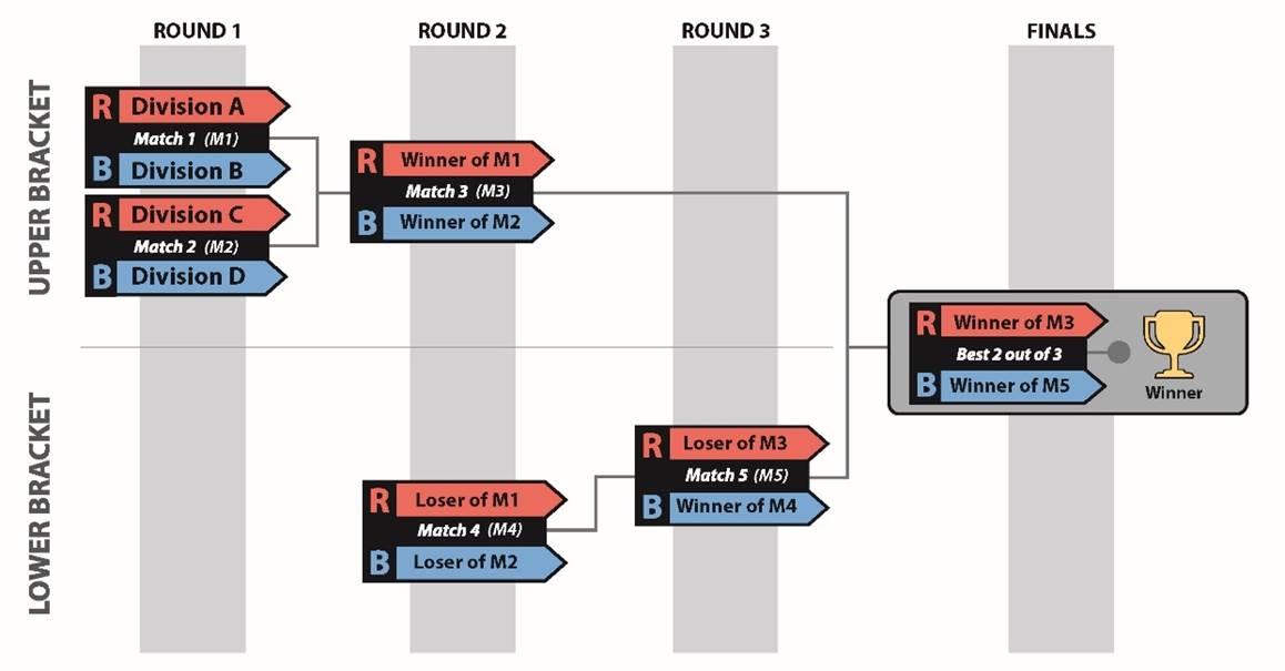
Figure 11‑5
2 division District Championship Playoff Bracket
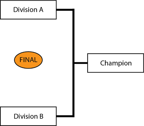
Table
11‑11 District Championship 4-ALLIANCE Playoff MATCH schedule
|
Match
|
Blue
|
Red
|
Blue Gap (minutes)
|
Red Gap (minutes)
|
Winner moves to
|
Loser moves to
|
|
Upper Bracket – Round 1 – Match 1
|
B
|
A
|
-
|
-
|
Red – Match
3
|
Red – Match
4
|
|
Upper Bracket – Round 1 – Match
2
|
D
|
C
|
-
|
-
|
Blue – Match 3
|
Blue – Match 4
|
|
15-minute Break
|
|
Upper Bracket – Round 2 – Match 3
|
W2
|
W1
|
17m
|
24m
|
Red – Match 6
|
Red – Match 5
|
|
Lower Bracket – Round 2 – Match
4
|
L2
|
L1
|
24m
|
31m
|
Blue – Match 5
|
|
|
15-minute Break
|
|
Lower Bracket – Round 3 – Match 5
|
W4
|
L3
|
17m
|
24m
|
6
|
|
|
15-minute Break
|
|
Finals - Match 6
|
W5
|
W3
|
17m
|
44m
|
|
|
|
15-minute Break
|
|
Finals - Match 7
|
W5
|
W3
|
17m
|
17m
|
|
|
|
15-minute Break
|
|
Finals - Match 8*
|
W5
|
W3
|
17m
|
17m
|
|
|
* if required
•
Each team on a Champion ALLIANCE of a 2-Division District
Championship Playoff tournament earns 10 points.
•
For a 4-Division District Championship Playoff tournament, each
team on a Champion ALLIANCE earns 20 points and each team on a Finalist
ALLIANCE receives 10 points.
•
If any of these alliances has recruited a BACKUP TEAM, these
points are divided amongst the teams as described in Section 11.8.1.3 Playoff Performance.
•
If an Alliance in a District
Championship Playoff has not yet recruited a BACKUP TEAM
per Section 11.7.3 BACKUP TEAMS, the Alliance Captain may
bring in only the highest ranked team from their division’s backup pool to join its Alliance.
At the 2023 FIRST Championship, teams are split into 8
divisions. The process used to assign teams to their division is as follows:
1. Rookies
are assigned randomly, team by team, sequentially to divisions (i.e. a team in
Division 1, a team in Division 2, a team in Division 3, a team in Division 4, a
team in Division 5, a team in Division 6, a team in Division 7, a team in
Division 8, then back to Division 1 again, until Rookies are all assigned to a division).
2. Step
1 is repeated with veteran teams.
Each division plays a standard tournament as described in Section 11.6 Qualification MATCHES and Section 11.7 Playoff MATCHES to produce the division
Champions. Those 8 division Champions proceed to the Championship Playoffs, on
the Einstein Fields, to determine the 2023 FIRST
Robotics Competition Championship Winners, per Section 11.9.4 FIRST Championship
Playoffs.
Details on how teams earn eligibility to attend the FIRST
Championship are posted on the FIRST
Championship eligibility webpage.
There is no provision for Backup
Teams at the FIRST Championship.
Instead, before each division Playoff Tournament, Alliances are selected per the process as described
in Section 11.7.1 ALLIANCE Selection
Process, however the process continues with a third round of selection as
follows.
Round 3: The same method is used
for each Alliance Captain’s
third choice except the selection order is reversed again, with Alliance 1 picking first and Alliance 8 picking last. This process results in 8 Alliances of 4 teams each.
Alliances may start with any
3 of the 4 Robots on their Alliance during division Playoff Matches and during the Championship Playoffs. Alliances submit Lineups for their matches as described
in Section 11.7.4
LINEUPS.
FIRST distributes buttons to the Alliance Captains during the Alliance Captain meeting, which takes place on the division
Fields. These buttons provide the necessary
access to the Arena for pit crew members.
T901 *Wear your buttons. Only team members wearing
proper buttons are allowed on the Arena floor
during division and Playoff Matches.
Violation: Match won’t
start until the situation is corrected. Those not displaying identification
must leave the Arena.
Teams should
assume they may be chosen for an Alliance and
think about the logistics of button distribution and set a plan prior to the Alliance selection process. It is each Alliance Captain’s responsibility to distribute
buttons to their pit crew members.
11.9.4
FIRST Championship Playoffs
The 8 division Champions play a Double Elimination style
tournament as described in Section 11.7 Playoff
MATCHES to determine the 2023 FIRST Robotics Competition Champions.
Exact match timing is provided
to FIRST Championship Playoff teams. ALLIANCES are paired as shown in Figure 11‑6.
Figure 11‑6
Championship Playoff Bracket
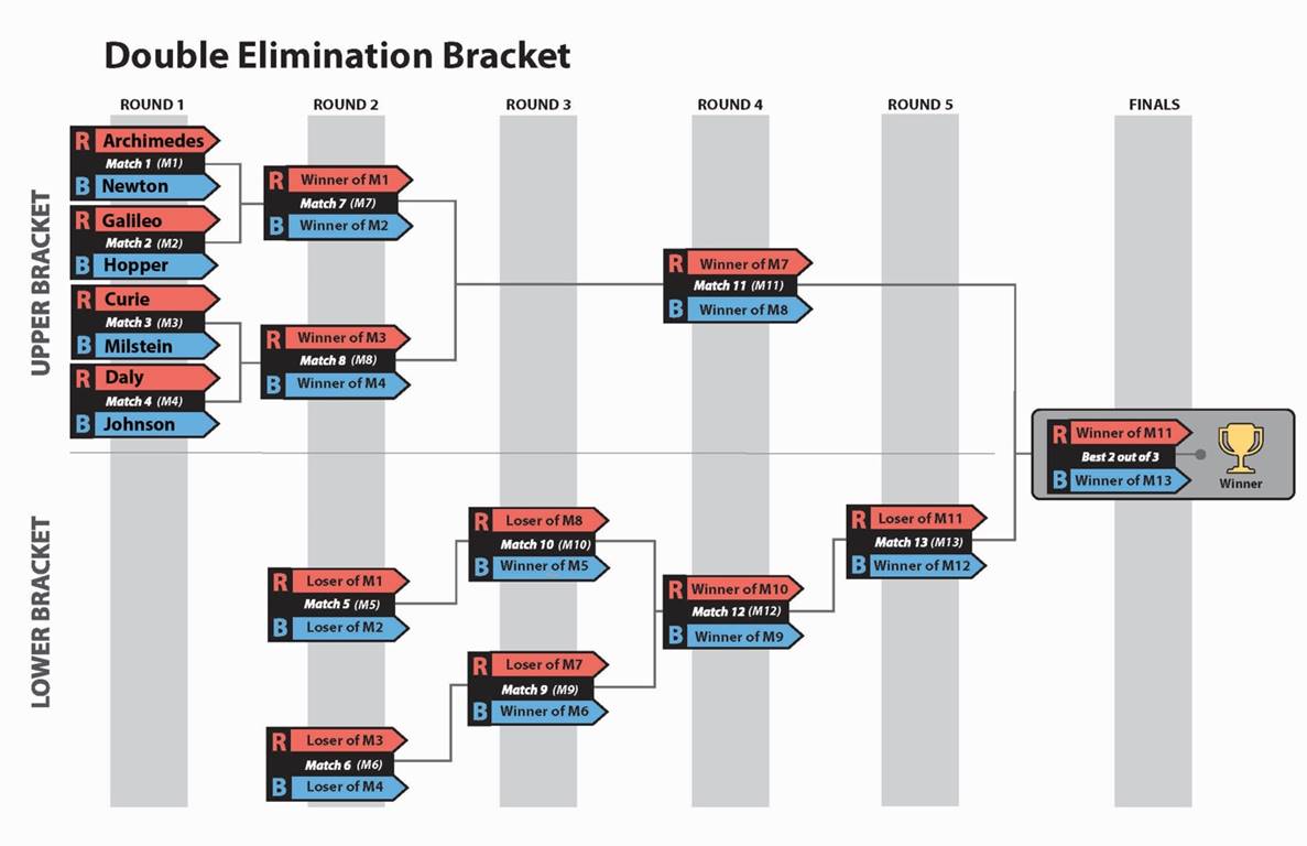
During the Einstein Finals, if the Match
score of each Alliance is equal, the Match is replayed. In this circumstance, the Lineup may be changed.
|
Term
|
Definition
|
|
ACTIVATION BONUS
|
At least 26 total CHARGE STATION points earned in AUTO
and/or ENDGAME
|
|
Active
Device
|
any device capable of dynamically controlling and/or converting a source of
electrical energy by the application of external electrical stimulus
|
|
Alliance
|
a cooperative of up to 4 FIRST Robotics Competition teams
|
|
Alliance
Captain
|
The designated student representative from each Alliance Lead
|
|
Alliance Area
|
a 20 ft. (~609 cm) wide by 9 ft. 10¼
in. (~300 cm) deep infinitely tall volume formed by, and including the
ALLIANCE WALL, the edge of the carpet, and ALLIANCE colored tape
|
|
Alliance
Wall
|
an arena element that separates ROBOTS from DRIVE TEAM
members in the ALLIANCE AREA. It consists of 3 DRIVER STATIONS.
|
|
Arena
|
a space which includes all elements of the game infrastructure that are
required to play CHARGED UPSM presented by Haas: the FIELD, GAME
PIECES, and all equipment needed for FIELD control, ROBOT control, and
scorekeeping.
|
|
Arena
Fault
|
an error in Arena operation
|
|
Auto
|
The first phase of each MATCH is 15 seconds long and called
the Autonomous Period (AUTO). During AUTO, ROBOTS operate without any DRIVE
TEAM control or input
|
|
Backup
Team
|
The team whose robot and drive
team replaces another robot and drive team on an alliance
during the Playoff matches
|
|
BACKUP POOL
|
the group of teams willing and able to join an alliance during the Playoff MATCHES, if needed, until up to 8
teams accept
|
|
BARRIER
|
a
7 ft. 4 in. (~224 cm) long assembly that separates each COMMUNITY from its
adjacent LOADING ZONE
|
|
Bumper
|
a required assembly which attaches to the Robot frame. Bumpers
protect Robots from damaging/being damaged by
other Robots and Field
elements
|
|
Bumper
Zone
|
the volume contained between the floor and a virtual horizontal plane 7½ in. (~19 cm)
above the floor in reference to the Robot
standing normally on a flat floor
|
|
Bypassed
|
the state assigned to any Robot which is unable
or ineligible to participate in that Match,
as determined by the FTA, LRI, or Head Referee
|
|
center
line
|
a white tape line that bisects the length of the FIELD.
|
|
charge STATION
|
an 8 ft. 1¼ in. (~247 cm) wide, 6 ft. 4⅛ in. (~193 cm)
deep structure that is located in each COMMUNITY such that its center is 8
ft. 2⅝ in. (~251 cm) from the far edge of the GRID’S tape line and
centered in the width of the COMMUNITY
|
|
Coach
|
a guide or advisor
|
|
community
|
an 18 ft. (~549 cm) wide by 11 ft. ⅜
in. (~336 cm) to 16 ft. 1¼ in. (~491 cm) deep infinitely tall volume formed
by the ALLIANCE WALL, the plane defined by the BARRIER plastic, ALLIANCE
colored tape, and the guardrail.an 18 ft. (~549 cm) wide by 11
ft. ⅜ in. (~336 cm) to 16 ft. 1¼ in. (~491 cm) deep infinitely tall
volume formed by the ALLIANCE WALL, the plane defined by the BARRIER plastic,
ALLIANCE colored tape, and the guardrail.an 18 ft. (~549 cm) wide by 11 ft. ⅜
in. (~336 cm) to 16 ft. 1¼ in. (~491 cm) deep infinitely tall volume formed
by the ALLIANCE WALL, the plane defined by the BARRIER plastic, ALLIANCE
colored tape, and the guardrail.
|
|
Component
|
any part in its most basic configuration, which cannot be disassembled without
damaging or destroying the part or altering its fundamental function
|
|
Continuous
|
describes rule violations that happen for more than
approximately 10 seconds
|
|
Control
|
the
state of a GAME PIECES if any of the
following are true:
A.
the GAME PIECE is fully supported by
the Robot, or
B.
the ROBOT is intentionally moving a GAME PIECE to a desired location
or in a preferred direction
|
|
CONE
|
a yellow 1 ft. ¹³⁄₁₆ in. (~33 cm) tall rubber marker cone
|
|
cone
NODE
|
a
1¼ in. Schedule 40 (1.66 in. (~4 cm) outer diameter) aluminum pipe with a
plug installed in the top
|
|
coopertition bonus
|
At least 3 GAME PIECES scored on each ALLIANCE’S CO-OP GRID
|
|
COTS
|
an
adjective that describes a standard (i.e. not custom order) part commonly
available from a Vendor for all teams for
purchase
|
|
Custom Circuit
|
Any active electrical item that is not an actuator
(specified in R501) or core control system item (specified in R710)
|
|
CUBE
|
cube-like shape, inflated to 9 ½ in. (~24 cm) +/- ¼ in. (~6
mm) as measured from face to face
|
|
CUBE NODE
|
a polycarbonate shelf that is 1 ft. 6¼ in. (~46 cm) wide and
1 ft. 5 in. (~43 cm) deep.
|
|
Disabled
|
the state in which a Robot is commanded to deactivate
all outputs, rendering the Robot inoperable
|
|
Disqualified
|
the state of a team in which
they receive 0 Match points and 0 Ranking
Points in a Qualification Match or causes
their Alliance to receive 0 Match points in a Playoff Match
|
|
dockED
|
The
state of the ROBOT if it is contacting only the CHARGE STATION and/or other
items also directly or transitively fully supported by the CHARGE STATION.
|
|
double substation
|
A SUBSTATION in-line with their opponent’s ALLIANCE WALL.
|
|
Driver
|
an operator and controller of the Robot
|
|
Driver Station
|
1 of 3 assemblies within an ALLIANCE WALL behind which a
DRIVE TEAM operates their ROBOT
|
|
drive
team
|
a
set of up to 5 people from the same FIRST Robotics
Competition team responsible for team performance for a specific Match
|
|
engageD
|
The state of the ROBOT if the following are true:
A.
the CHARGE STATION is LEVEL, and
B.
all ALLIANCE ROBOTS contacting the CHARGE
STATION are DOCKED.
|
|
Fabricated
Item
|
any
Component or Mechanism
that has been altered, built, cast, constructed, concocted, created, cut,
heat treated, machined, manufactured, modified, painted, produced, surface
coated, or conjured partially or completely into the final form in which it
will be used on the Robot
|
|
Field
|
an approximately 26 ft. 3½ in. (~802 cm) by 54 ft. 3¼ in.
(~1654 cm) carpeted area bound by and including the inward- and upward-facing
surfaces of the guardrails, inward-facing surfaces of the ALLIANCE WALLS,
inward-facing surfaces of the SINGLE SUBSTATION (excluding the PORTALS), and
the outermost vertical and diagonal polycarbonate surfaces of the DOUBLE
SUBSTATION (excluding the PORTALS)
|
|
Field
Staff
|
Referees, FTAs, or
other staff working around the Field
|
|
FMS
|
all electronics responsible for sensing and controlling the FIRST
Robotics Competition Field
|
|
Foul
|
a credit of 5 points towards the opponent’s Match point
total
|
|
Frame Perimeter
|
fixed, non-articulated structural elements of the Robot contained
within the Bumper Zone
|
|
FTA
|
a FIRST
Technical Advisor
|
|
game pieces
|
CONES and CUBES
|
|
grid
|
a
3 ft. 10 in. (~117 cm) tall, 4 ft. 8¼ in. (~143 cm) deep assembly that
includes the ALLIANCE colored tape line
|
|
Human Player
|
a GAME PIECE manager
|
|
hybrid
node
|
1
ft. 4 in. (~41 cm) deep carpeted surface contained within the GRID.
|
|
Inspector
|
a volunteer employed to accurately and efficiently assess the legality of a
given part or robot
|
|
KOP
|
Kit
of Parts, the collection of items listed on the current season’s Kickoff Kit
Checklists, distributed to the team via FIRST Choice in the current
season, or paid for completely (except shipping) with a Product Donation
Voucher (PDV) from the current season
|
|
level
|
A CHARGE STATION within approximately 2½° of parallel to FIELD carpet
|
|
Lineup
|
the
list of the 3 teams participating in the Match
and their selected DRIVER STATIONS
|
|
LINK
|
3 adjacent NODES in a ROW contains a scored GAME PIECE
|
|
LOADING
ZONE
|
an 8 ft. 3 in. (~252 cm) wide by 11 ft. ¼ in. (~336 cm) to 22
ft. ¼ in. (~671 cm) deep infinitely tall volume formed by the DOUBLE
SUBSTATION, the plane defined by the BARRIER plastic, the guardrail, and
ALLIANCE colored tape. The LOADING ZONE includes the tape.
|
|
LRI
|
a Lead Robot INSPECTOR
|
|
Major
Mechanism
|
a group of Components and/or Mechanisms assembled together to address at least 1
game challenge: Robot movement, GAME PIECES manipulation, Field
element manipulation, or performance of a scorable task without the
assistance of another Robot
|
|
Match
|
a two minute and 30 second period of time in which Alliances play CHARGED UP
|
|
Mechanism
|
an assembly of Components that provide specific
functionality on the Robot
|
|
mobility
|
The award given to a ROBOT whose Bumpers have completely left its Community at any point during AUTO
|
|
Momentary
|
describes rule violations that happen for fewer than approximately 3 seconds
|
|
MXP
|
myRIO Expansion port, the expansion port on the roboRIO
|
|
node
|
1 of 9 GAME PIECE scoring locations within a GRID
|
|
Operator Console
|
the set of Components and Mechanisms used by the Drivers
and/or Human PlayerS to relay commands to the
Robot
|
|
PARK
|
the
state of a ROBOT whose BUMPERS are completely contained within its COMMUNITY
but does not meet the criteria for DOCKED
|
|
Passive Conductor
|
any device or circuit whose capability is limited to the
conduction and/or static regulation of the electrical energy applied to it
(e.g. wire, splices, connectors, printed wiring board, etc.)
|
|
PH
|
a
Pneumatic Hub
|
|
PCM
|
a Pneumatic Control Module
|
|
PDH
|
a
Power Distribution Hub
|
|
PDP
|
a Power Distribution Panel
|
|
Pin
|
the
act in which a Robot is
preventing the movement of an opponent Robot
by contact, either direct or transitive (such as against a Field element)
|
|
portal
|
a three-dimensional volume through which humans transfer
GAME PIECES to ROBOTS or the FIELD
|
|
Red
Card
|
a penalty assessed for egregious Robot or team member
behavior or rule violations which results in a team being Disqualified for the Match
|
|
Referee
|
an official who is certified by FIRST to enforce
the rules of CHARGED UP
|
|
Repeated
|
describes rule violations that happen more than once within a Match
|
|
Robot
|
an electromechanical assembly built by the FIRST Robotics Competition team to play the current season’s game and includes all
the basic systems required to be an active participant in the game –power,
communications, control, Bumpers, and
movement about the Field
|
|
ROW
|
a series of 9 horizontally adjacent NODES where GAME PIECES can be scored for a
common number of points
|
|
RP
|
a Ranking Point
|
|
RPM
|
a
Radio Power Module
|
|
RS
|
the Ranking Score
|
|
RSL
|
a Robot Signal Light
|
|
Signal Level
|
circuits which draw ≤1A continuous and have a source
incapable of delivering >1A, including but not limited to roboRIO non-PWM
outputs, CAN signals, PCM/PH Solenoid
outputs, VRM 500mA outputs, RPM outputs, and Arduino outputs)
|
|
STAGING
MARK
|
1 of 8 marks used to identify starting locations for GAME
PIECES
|
|
Starting Configuration
|
the physical configuration in which a Robot starts a Match
|
|
Starting
Line
|
a white tape line spanning the ALLIANCE AREA and SUBSTATION AREA located 2 ft. 4 in.
(~71 cm) from the face of the ALLIANCE WALL
to the near edge of the tape.
|
|
Student
|
a person who has not completed high-school, secondary
school, or the comparable level as of September 1 prior to Kickoff
|
|
single
substation
|
a
SUBSTATION in-line with the guardrail.
|
|
substation
|
an assembly used to move GAME PIECES from humans to ROBOTS
or onto the FIELD. There are 2 types of SUBSTATIONS in each SUBSTATION AREA:
a SINGLE SUBSTATION and a DOUBLE SUBSTATION.
|
|
Surrogate
|
a team
randomly assigned by the Field Management
System to play an extra Qualification Match
|
|
sustainability bonus
|
At least 6 LINKS scored.
|
|
Tech
Foul
|
a credit of 12 points toward the opponent’s Match point
total
|
|
Technician
|
a resource for Robot
troubleshooting, setup, and removal from the Field
|
|
Teleop
|
The
second phase of each MATCH lasting two minutes and fifteen seconds (2:15) during
which DRIVERS remotely operate ROBOTS to retrieve and score GAME PIECES
|
|
Vendor
|
a legitimate business source for COTS
items that satisfies all criteria listed in Section
9
|
|
VRM
|
a
Voltage Regulator Module
|
|
Yellow Card
|
a warning issued by the Head Referee
for egregious Robot or team member behavior
or rule violations. A subsequent Yellow Card
within the same tournament phase results in a Red
Card
|
FIRST®, the FIRST® logo, FIRST®
Robotics Competition, FIRST® Tech Challenge, CHARGED UPSM,
FIRST ENERGIZESM, Gracious Professionalism®, and Coopertition®
are trademarks of For Inspiration and Recognition of Science and Technology (FIRST).
LEGO® is a trademark of the LEGO Group. FIRST®
LEGO® League is a jointly held trademark of FIRST and the
LEGO Group. All other
trademarks are the property of their respective owners. ©2023 FIRST. All
rights reserved.